A standout classic.
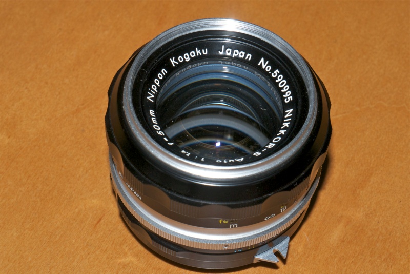
The 50mm Nikkor-S f/1.4. One of the most beautiful optical masterpieces yet conceived.
Where Leitz’s contemporary chromed Summilux is all about elegance and grace when it comes to looks, the Nikkor-S boasts an unrestrained machismo. Clearly, you could give someone a fair old whack with it then use the same blunt instrument to take their picture!
The 50mm Nikkor-S f/1.4 lens is an affordable classic. Mine ran me $144 in near-mint condition, plus $25 for Ai conversion by John White, and $30 for a CPU. The lens is abundantly available in just about any condition on the used market. Given its low price, it’s false economy to buy a beater. This 50mm pre-Ai lens was made between March 1962 and June 1974, with the last batch, made in 1973-74, marked ‘S.C’ denoting multi-coating. The first S.C ones were in an all metal barrel, the last adopted the awful plastic covered version. Thereafter, the formulation changed from 7 elements in 5 groups to 7/6, and Ai and Ai-S versions came along. Mine is a single-coated 1971 example. As is the case with all pre-Ai Nikkors, construction quality is simply unrivaled. Fit, finish, materials, engraving and cosmetics are all top notch.
The front element is large, and though somewhat recessed, the lens gains from a lens hood, especially with the earlier single-coated versions. I have a period Nikon HS-9 hood on mine. Filters are Nikon’s standard 52mm diameter
The lens shows some vignetting on full frame (none on APS-C) fully open which disappears completely by f/4. My lens correction profile fixes that and you can download it here. Such modest chromatic aberration as there is can be easily removed by making sure the appropriate box is checked in your file import setup. Diffraction is very minor at f/16, with the highest resolution being delivered in the range f/2.8 through f/11. The seven sided aperture makes for attractive rendering of out-of-focus areas.
Performance at full aperture needs no excuse, and is fully usable, with resolution good enough for large prints right to the corners. By f/2.8 it’s as sharp as it gets.
CPU installation – not for the faint of heart:
Unless you are very comfortable with tinkering, CPU installation in this lens should be delegated to an expert. The rear baffle is 1.548″ in diameter, well in excess of the limit of 1.427″ which permits a straight glue-on of the CPU to the baffle. If you are doing the job, first mark the position of the CPU on the flange using a scribe or pin (“limit lines”). You need to remove the baffle metal in the location of the CPU. The baffle is set-off 0.03″ from the moving rear lens optical assembly and is 0.13″ thick. Thus, removing the baffle material reduces the effective diameter by 0.13″ from 1.548″ to 1.418″, (the 0.01″ clearance is retained) which is ideal for proper CPU clearance. I have found the range of 1.363″ through 1.427″ works fine, with play being taken up by the sprung contacts on the CPU.
To install a CPU you must first remove the baffle and flange as one assembly. Do not separate the baffle from the flange. Leave the two very small radial countersunk screws untouched. Of the five slotted screws retaining the chromed bayonet flange, remove four. Use a really tight-fitting, professional miniature screwdriver. I use, and recommend, the set which comes from Wiha. You want the screwdriver to be a really tight fit across the whole width of the slot in the screw. Anything less risks damage.
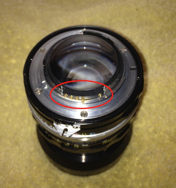
Do not remove the red circled screw, illustrated below.
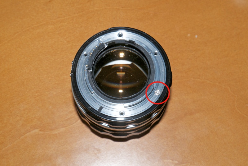
Do not touch this screw. If you must, loosen it, but do not remove it.
If you look really hard, you will see that the slot in this one is shallower than in the other four. This screw retains the aperture return tensioning spring, and you must leave it intact. It is retained by a small threaded brass post on the inside of the flange. The post is accommodated by a recess in the inside of the lens. The related screw does not retain the bayonet flange to the body of the lens.
When you remove the flange you will see the spring mechanism where it is retained by this screw and also the attachment point of the other end of the spring on the aperture setting claw which slides around the periphery of the flange. The stop down lever is the only part of this claw assembly which protrudes through the flange.
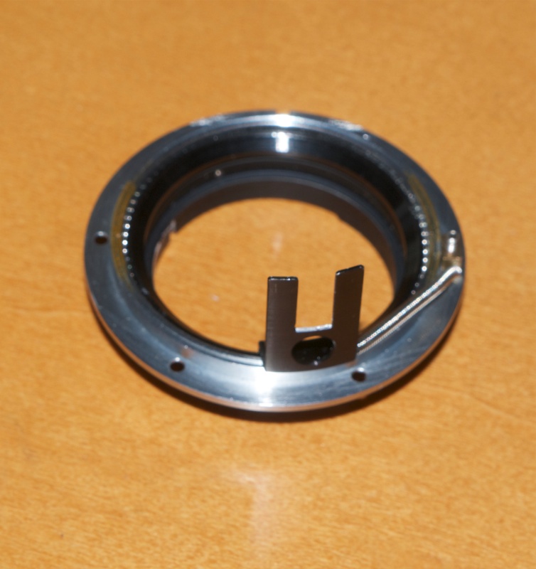
The aperture claw on the inside of the flange. The spring returns the diaphragm to maximum aperture.

The spring retaining nut goes in the red orifice. The claw goes in the green one after
checking that it mates with the (chrome – barely visible) aperture tab inside the body of the lens.
With the flange removed I used a Dremel tool with a cut-off wheel to remove the flange in the location of the CPU.
They don’t make them like this any more:
When I had the rear bayonet flange off to do the machining for the CPU, I noted several fine abrasive stone touch up marks where the flange’s thickness and planeness had been adjusted manually as part of final assembly. This is what makes these so consistent and so good, and indicates a process of manual fine tuning on final assembly prohibited by modern skilled labor costs.
The cuts:
The arc of your longitudinal cuts is denoted by the previously marked scribed limit lines. The depth of the cut is such that the flange is removed to a point flush with the chromed body of the flange. When replacing the flange, you will see two circumferential cut-outs in the rear of the lens. The smaller one is for the post/screw/spring assembly. the longer of the two is for the aperture actuation claw attached to the flange. Look down the longer slot. You will see a small chrome tab. This is where you must insert the claw when replacing the flange. The claw will mate with the tab and restore aperture operation. If you do this wrong, and miss the chrome tab, your lens will remain stuck at full aperture. Guess how I know!
In the following picture I have shown the flange replaced on the lens to show the cut-out baffle material. Before replacing the flange screws, I checked that the aperture control worked properly.
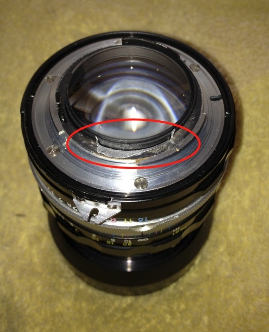
The bayonet flange back in place after removing the arc of baffle metal.
With the flange tightened down again, I did a dry run with the CPU, installing it with two-sided sticky tape applied to the flat side of the CPU, not to the concave curved side. The concave side must clear the lens barrel which moves longitudinally as the lens is focused. With the sticky tape temporary installation, I inserted the lens in the D700 and did the usual CPU programming.
CPU in position using two-sided sticky tape, for testing fit and for programming.
Epoxy:
Permanent installation using two-part epoxy is next. The next precaution to take is to be absolutely certain that no epoxy glue squeeze-out from the CPU/flange mating surfaces makes its way onto the lens barrel. If it does, your lens will be trashed, as the lens barrel containing the optics will be glued to the flange and CPU. You will be unable to focus the lens. Accordingly, I took the simple precaution of interposing a piece of writing paper between the flange and lens barrel as shown below. I tucked this in as far as I could.
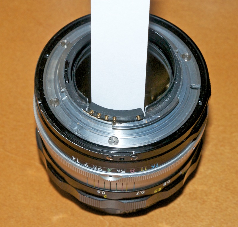
Paper insert protects the lens barrel from glue squeeze-out.
As you can see, I have removed the ugly external ‘claw’ on the
aperture ring (two small screws) which serves no purpose on the D700.
With the lens at infinity (to retract the barrel to the maximum and provide a reference for the radial positioning of the CPU), epoxy applied and the CPU in place and snugged up against the inserted piece of paper, I was unconcerned about glue squeeze-out between the inside of the CPU and the barrel with the optics. In fact I had some squeeze-out (on the second attempt – see ‘Be Careful!’ below) and the paper was seized when the epoxy cured. I simply removed the flange and pulled the paper off from the inside of the flange, leaving a nice glue squeeze out line shaped to fit – but not touch – the barrel. The clearance is thus one paper thickness. Not much, and certainly not a job for the nervous or cack-handed.
When replacing the flange, I first made sure that the holes in the flange aligned exactly with the threaded sockets. Then I took care to tighten the four retaining screws in a criss-cross pattern, in three stages of increasing tightness, to avoid any possibility of distorting the flange.
The result works perfectly and the CPU is well protected by virtue of its partial recess in the baffle.
Be careful!
So there I was, banging away merrily with the newly chipped lens, thinking all was right with the world, when I noticed the exposure data in the finder had suddenly gone badly awry. Instead of apertures I was getting whole numbers. I whipped the lens off and …. found the CPU merrily lying about in the well of the mirror box. It had come off! Well that does it, says I, no more Mr. Nice Guy, so I set to the son-of-a-gun with fresh epoxy and a woodworker’s clamp, after giving the mating surfaces a good scrubbing with a final wipe using isopropyl alcohol to remove all traces of grease.
The first time I glued the CPU I was careful not to get any glue squeeze-out between the inside of the CPU and the lens barrel. This time I decided to have some, reckoning that the protective paper, used while the epoxy was drying would prevent seizure. It did. Once dry, I removed the bayonet flange one last time and removed the protective paper from the inside of the CPU. The greater amount of epoxy and the squeeze-out line gives a stronger result.

No more Mr. Nice Guy.
This time it looks like it’s going to hold. I gave it a fair bashing about in the field, never babying it when changing lenses, and the CPU is still in place. I’m just counting my lucky stars that the mirror didn’t go smashing into it when it came off.
Lens correction profile:
You can download the profile here.
With aperture control passed to the lens, as is normal for pre-Ai-S optics, here are eight test snaps from f/1.4 through f/16. You can see the vignetting clearly in the first three at f/1.4, f/2 and f/2.8. Accordingly, the lens correction profile I have made contains four files – at f/1.4, f/2, f/2.8 and f/4. The f/4 profile is automatically applied from f/4 through f/16.
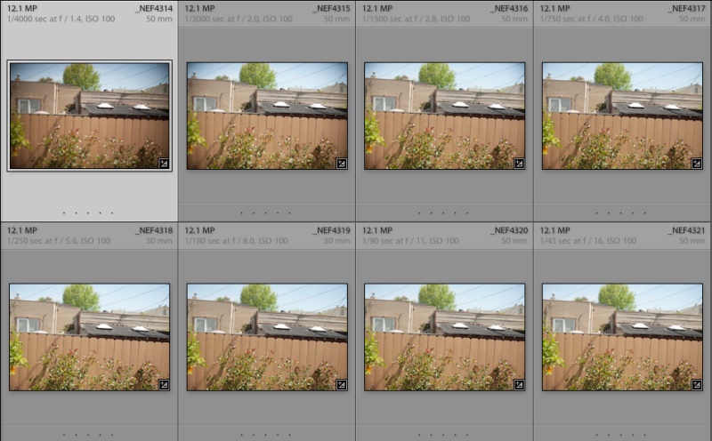
Eight test shots with CPU installed, ‘A’ exposure automation.
No lens correction profile was used here. Vignetting disappears by f/4.
Importing the same pictures, with the lens correction profile activated, completely eliminates corner vignetting at the three largest apertures:
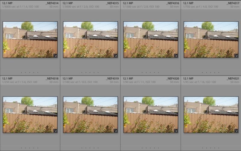
Eight test shots with CPU installed, ‘A’ exposure automation.
With lens correction profile applied. No vignetting visible at any aperture.
Note the evenness of exposure over a range of eight apertures (using the automatic ‘A’ mode – aperture priority) with aperture settings controlled by the lens. Use of the lens correction profile makes an already great lens that much better.
In tomorrow’s article I will illustrate how to fine tune the illumination point of the viewfinder focus LED in the D700 (and other bodies) using programmable settings in the CPU. Nailing perfect focus at f/1.4 is key to extracting the very best results from this great lens. Those not needing f/1.4 should look to the 50mm f/2 Nikkor-H which is every bit as capable, smaller, lighter and much cheaper while permitting simple glue-on CPU installation.
Early snaps made using this lens are here and here, now that I have established that my CPU will not fall off again …. The 50mm f/1.4 is to Nikon what the 50mm Summicron f/2 is to the rangefinder Leica. A classic masterpiece of optical design and mechanical engineering which defines the marque. I expect my son to be using this one long after I’m six feet under, pushing up the daisies.