Addressing the 24″ iMac.
While the logic board from a 20″ late-2006 iMac is out for repair (update here, I received the Nvidia 7600 graphics card – purportedly new – from ApplePalace.com – $263 with tax and shipping to my CA address. This is for my late-2006 24″ iMac. The graphics in both machines are shot. The vendor had assured me when I called that the part was new and came with a 60 day warranty; the invoice states 30 days. Either way, that’s enough to install and test it.
So, using the Apple Manual for this model, found here, I dismantled the computer and took a look around. First, the machine is quite a bit easier to take apart than the 20″ model. No secret catches for the bezel, no black tape everywhere and no need to remove the optical drive to extract the mother board.
Whereas the GPU in the 20″ and 17″ models is soldered to the logic board, in the 24″ model it’s plugged in and retained with three screws. Apple offered the machine with a 2.16gHz C2D/Nvidia 7300 combination or with a 2.33gHz C2D/Nvidia 7600 pairing. I bought the latter card as the replacement, as it has twice the video ram at 256mB, so I will end up with a 2.16gHz/Nvidia 7600 iMac. GPU speed/memory is far more important for graphics intensive activities like photo processing, so this seems to make sense. With CA tax, the premium for the 7600 model is $50, both new.
As with the 20″ iMac, simply replacing the part makes no sense. The problem – inadequate cooling – will not go away and you will likely be doing the same thing all over again and, like a bad mechanic, simply throwing money at the problem. Better cooling is required.
As my 24″ iMac is worked very hard for both business and pleasure, I decided to go the whole hog and drill cooling holes for the GPU radiator, the power supply and the hard disk drive. (I only addressed the first two on the 20″ model as it has a far easier life and the HDD is the least troubling of the three when it comes to heat issues.) Those are the three greatest heat generators, in that order. As there’s much more space in the 24″ iMac’s body, the design of the GPU cooling splits the cooling between the GPU and the GPU Diodes with separate radiators, mounted above one another. As in the 20″, a fan blows air across the fins to confer cooling and copper pipes are again used to conduct heat from the GPU and diodes. The snag is that the hot air emanating from the GPU and diodes blows directly on the power supply above! (In the 20″ the power supply is off to the side.) No wonder the latter gets hot – it has no cooling fan of its own.
When I purchased the iMac (used – documented in this blog in detail) I immediately installed a 1 terabyte Samsung hard disk drive. The HDD is cooled by its own fan but also runs hot, so I decided to provide cooling holes for the HDD also. I have no comparative data as to whether a 1 tB drive runs warmer than the 250 gB Western Digital junk Apple installed in these models, but the additional labor to cool the HDD is, in any case, minor.
The layout of the components in the 24″ model differs from that in the 20″ model, so the following self-explanatory pictures will help you to determine where to drill holes. As before, the grid is 3/4″ and the holes 3/8″.
The whole logic board still has to be removed to get at the exchangeable GPU, which is screwed to the back (three screws) and very firmly clipped in to the connector on the logic board. There’s no way you can get replacement wrong as the two screws on the circuit end of the assembly will not fit if a proper connection has not been made between the GPU and logic board. Mine needed a firm push and engaged with a ‘click’,
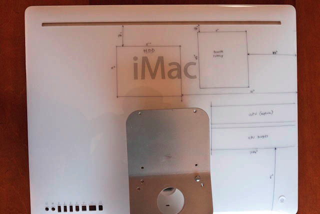
Overall layout
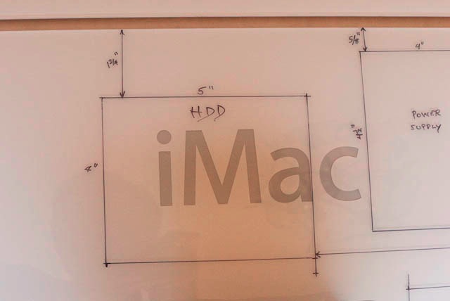
Hard Disk Drive

Power Supply
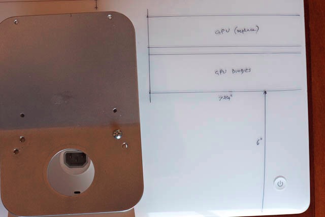
GPU and GPU Diode radiators – the plate on the left is for wall mounting
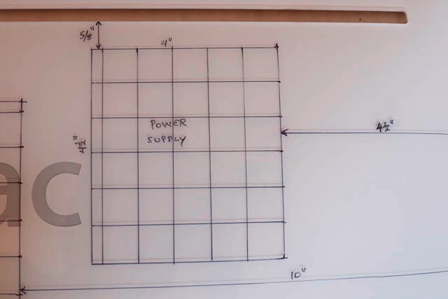
Grid for the Power Supply
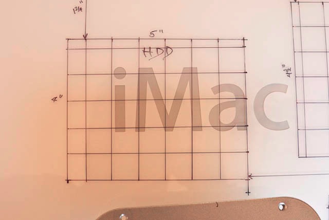
Grid for the HDD
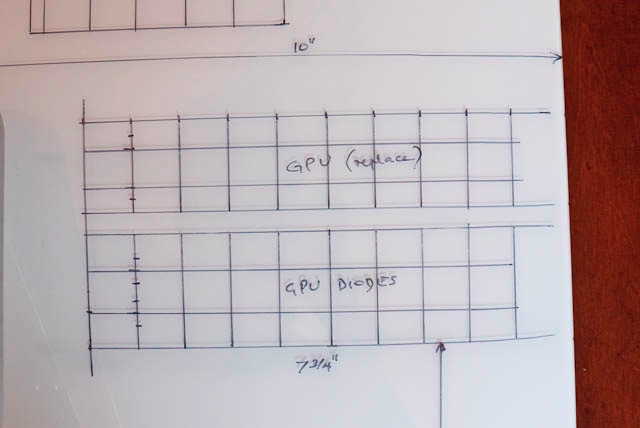
Grids for the GPU and GPU diodes
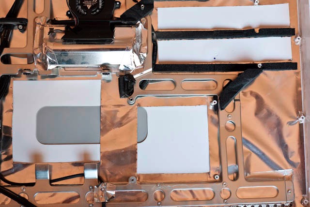
Inside view showing silver paper cut away
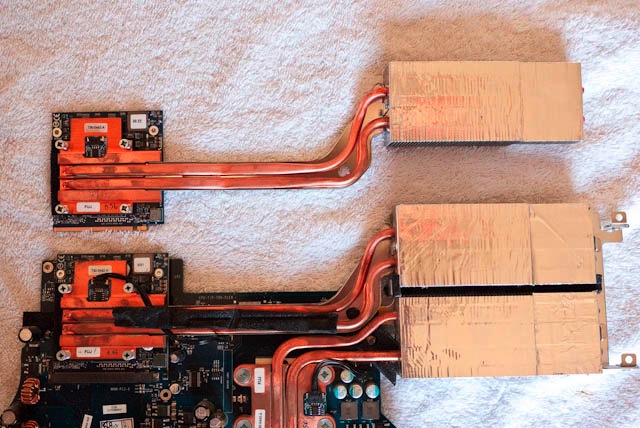
Old GPU on logic board, new above
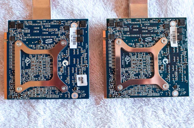
Rear of GPUs – new on left distinguished by ‘256’ label
The rest of the procedure is much as for the 20″ model described in Part II. That is, once drilled, the holes are de-burred and high temperature Loctite adhesive is used to retain aluminum mesh on the inside to act as a dust shield.
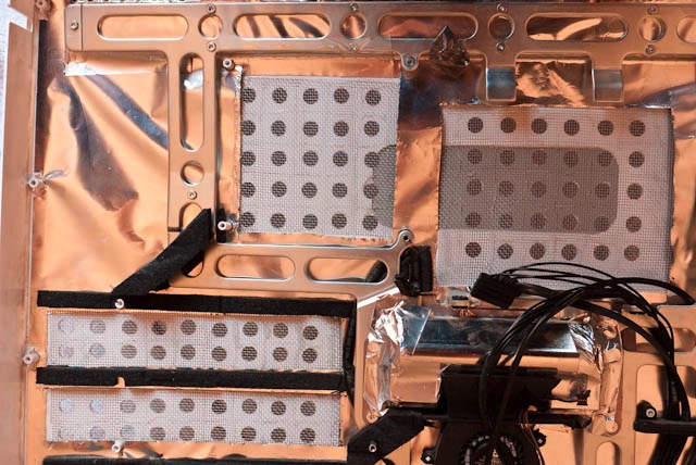
The wire mesh glued in place
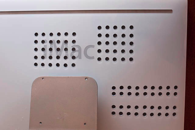
The final result – Sharpie markings have been removed with Isopropyl alcohol
I wore out two more Forstner bits doing this in addition to the one worn out on the 20″ iMac. Seems they are good for 40-45 holes each before giving up the ghost.
If you want to install a larger HDD in your iMac, now would be a good time.
My one fear is that the diodes for the GPU, are also fried. Those are soldered to the logic board so if the problem does not go away (slow downs, beachballs, etc.) then the mother board itself will have to be sent in for repair. Even so, I will end up with a machine with, hopefully, significantly enhanced graphics performance – and proper cooling.
A few words on thermal paste:
There is no magic to thermal (or heat) paste. Its purpose is to enhance contact between two surfaces – one a heat generator, the other a heat sink. It simply fills the microscopic imperfections in the surfaces with its conductive medium and, when the two are squeezed together, optimizes transfer of heat from generator to sink.
The 20″ and 24″ iMacs use two radiators – one for the GPU, the other for the GPU diodes. Both terminate in copper plates (heat sinks) which are in intimate contact with the GPU and GPU Diode, respectively. And between each is a thin layer of thermal paste.
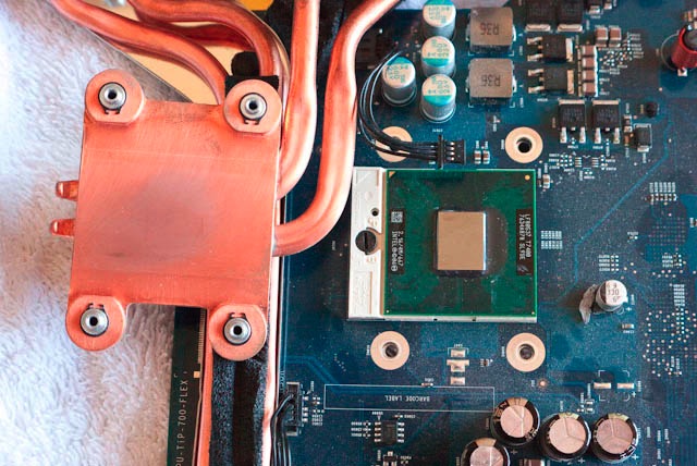
In the 20″ both surfaces must be cleaned and new thermal paste applied. In the 24″, if you are just changing the Nvidia GPU, the replacement GPU comes with thermal paste installed and need only be plugged in and screwed down. However, there’s no harm in renewing the thermal paste for the GPU diode whose radiator/heat sink is fastened to the mother board with four T8 screws through the heat sink (a copper plate) and one through the side of the radiator. Remove these five screws and follow the next three pictures, after disconnecting the small cable attached to the heat sink circuitry.
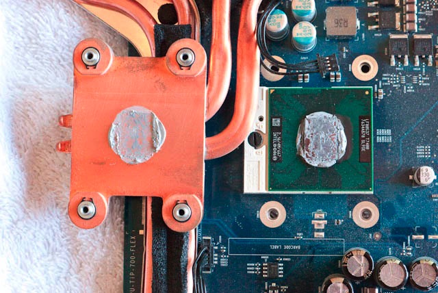
Old thermal paste – note the squeeze out. Note the detached cable also.
Surfaces cleaned with Isopropyl alcohol and a Q tip
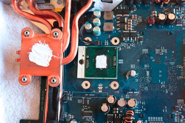
New thermal paste applied – I removed some as this is a bit too much!
Don’t forget to reconnect the cable or your graphics will be well and truly dead!
‘Experts’ will regale you with the right amount to put on but that’s all nonsense. Just make sure you have enough to cover both contact surfaces so that the base material does not show through (OK, a little less than I used above!) and then tighten down the heat sink. The design is optimized to ensure just the right amount of pressure between diode and heat sink using those nicely engineered sprung posts, and any excess will simply squeeze out. How do you think the squeeze out in the first of the above three pictures happened in the first place? Just don’t mess with the adjustment of the sprung posts.
Once I have everything together I will post a piece on performance for both the 20″ and 24″ machines.