Doing it right.
For an index of all my Mac Pro articles, click here.
If you examine the three model years and six versions of the current Mac Pro – 2009, 2010 and 2012 – each of which came in single or twin CPU models – only one of these uses a non-standard Intel Xeon CPU design. The odd duck is the 2009 dual CPU version which uses CPUs without the Integrated Heat Spreader (IHS), an alloy top plate which is both glued and soldered to the CPU and the surrounding base itself. I have read no definitive reasons for this approach and would guess that Apple must have been concerned about thermal performance, the no-IHS design likely being easier to cool with the massive heat sinks used in the Mac Pro. What is mystifying is that the 2010 and 2012 dual Mac Pros reverted to stock IHS CPUs with little or no other apparent changes, other than to the height of the heat sinks to accommodate the thicker CPUs and reversion to stock sprung CPU retainers.
You can see the difference in Apple’s own drawings in their service manuals:
Single and twin CPU retainer in all except the 2009 dual models.
This is the standard sprung retainer used in most Intel CPU installations
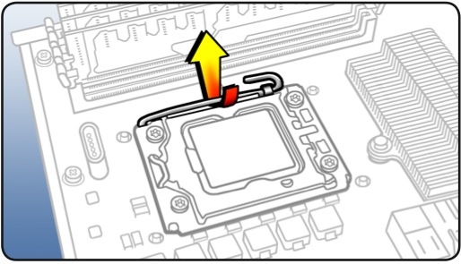
Dual CPU design in the 2009 8-core – no IHS.
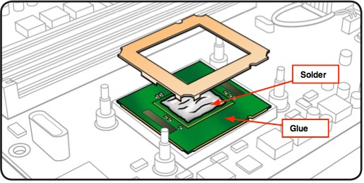
My annotations refer to the IHS design,
showing how the IHS is attached.
The practical upshot of the dual CPU 2009 design difference is that upgrading the CPU means that the heat sinks must be raised 2mm, a process fraught with risk of damage to the relatively fragile CPU socket, if not to the CPU itself. A damaged socket means a new processor board, some $400, and loss of use while you wait for the replacement. That and a bruised ego, not to mention time wasted.
Additionally, revisions have to be made to the heat sink fan power connectors and additional thermal pad material must be installed on the voltage regulators to maintain proper thermal contact with the heat sinks. Finally, fresh threadlocker should be applied to the retaining bolts for the heat sinks, as I illustrate.
In mechanical tasks proper instructions never use the word ‘judgment’. Judgment is subjective. ‘Subjective’ translates, as often as not, to catastrophe. Thus, in determining a measured approach to CPU upgrades in the dual 2009 machine, I set forth a low risk, objective way of securing the heat sinks with the upgraded, thicker CPU in place which will protect those fragile CPU sockets from damage.
Yet, clearly, the most elegant way of doing the 2009 dual upgrade is to use upgraded CPUs without the IHS fitted. The snag is that Intel appears never to have marketed these. This has caused determined upgraders to use various methods to remove the IHS, including razor blades, unmanaged heat, force and abrasive means to emulate the stock Xeon E5520 design.
The advantages of this approach are that the upgraded CPU is simply dropped into the socket, the loose alloy frame is placed over the CPU and the heat sinks are reattached with exactly the same number of bolt turns as was required to remove them. No changes are needed to the temperature sensor sockets in the heat sink and no additional thermal pad material need be installed. Nice and simple.
The disadvantage is that the IHS removal process is high risk. The risk includes mechanical damage to the CPU and financial damage to your pocket-book if you get it wrong. And it is not easy.
Reader Paul Opsahl had purchased a 2009 dual CPU Mac Pro after seeing my series of articles on this exceptional bargain of a computer. When Paul mentioned that he had managed to remove the IHS plates in the two Xeon W5590s he used in his 2009 dual upgrade, I was all ears. I asked him to detail his method and I think you will find it makes for fascinating reading. As the IHS is both soldered and glued to the CPU and the printed circuit board, some razor blade work remains but Paul’s technique to remove the solder bond is obviously the right way to do this, and I present his work below.
You will find Paul’s approach rigorous and well researched – in marked contrast to the amateur hour methods found on the many chat boards out there. You will also be amazed at just how shoddy Intel’s soldering technique is – maybe reason enough for Apple to adopt a non-IHS design in the first place!
If you want to install upgraded non-IHS CPUs of your choice in a dual 2009 Mac Pro, and want do do it right with non-IHS CPUs, contact Paul and see if he can fit you in while doing his day job and keeping bread on the table. You will find his rates for the work of removing the IHS reasonable. Regard the payment you make to him as the cost of insurance against damaging the CPU sockets in the processor board of your precious Mac Pro. Paul is an electronics engineer, not a backyard hacker, and has the right tools for what is a difficult job.
Paul takes it from here.
Preliminary discovery:
I started with a visit to the local computer recycler (Midwest Computer Brokers) in Walford, IA. I asked if they had any old Xeon processors available – any speed. I explained that I wanted to learn how to successfully remove the IHS. They gave me a Pentium 4 processor that already had the IHS removed with the aid of a blow-torch and a flat blade screwdriver. I decided that I could use that in a first experiment to determine what temperature the solder melts at ( more on that later ).
During a second trip to MCBIA, I specifically asked for a Xeon processor with the IHS intact. They offered to sell me a known good Dual Core 3.03GHz Xeon for $40. The goal with that device was to learn how to cut through the adhesive without damaging the printed circuit board and remove the IHS using a temperature controlled heat plate. I had seen a post where someone had used a double-edge razor for this purpose. I opted for a single-edge razor thinking there would be less chance for me to see blood. The single-edge blade worked, but I later learned that the single-edge blades are almost twice as thick as the double-edge blades ( the double-edge blades I used later on the Quad Core Xeon processors are approximately 0.004 inches thick ). The adhesive is very soft, but tightly compressed between the IHS and the rigid printed circuit board in a gap of about 0.008 inches. That narrow gap means that it’s tough to get even the thinnest razor blade between the IHS and circuit board. It took several passes to get to the point where I sensed that the blade was no longer cutting adhesive. Having access to the dimensions of the adhesive spread would have helped here. Based on a visual inspection of the adhesive using a microscope, I concluded that the IHS was cut free ( except for the solder ). There is a place on one side where the adhesive is absent – mostly likely to allow cleaning solution to escape from under the IHS during assembly.
Temperature controlled heat plate with vacuum:
At that point, I was ready for the temperature controlled heat plate. During my experiment with the Pentium 4 processor, I placed the already removed lid upside down on the heat plate and slowly increased the temperature until the solder melted. The heat plate is controlled with a digital thermostat that makes this measurement quite easy.
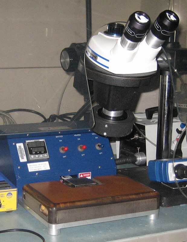
The hot plate and microscope at work.
That experiment indicated that 165 degrees C was the temperature I should use during this second experiment. Confident that Intel had used the same type of solder to attach the IHS to a Xeon processor, I set the temperature to 165 degrees C and waited until the temperature controller indicated that the heat plate had reached 160 degrees C. At that temperature, I turned on the vacuum pump that holds the device in place via a small hole in the center of the heat plate and placed the processor on the heat plate with the IHS side down. This technique limits the amount of heat absorbed by the assembly. I started applying a very light upward force on the printed circuit board using a tweezer – just enough to lift it away from the CPU when the solder had melted. The temperature of the heat plate continued to slowly increase – after about 20-30 seconds, the solder flowed and the printed circuit board lifted away from the IHS. I lifted the printed circuit board away and placed it to the side to cool.
Post-removal inspection:
During inspection of the remaining solder on the CPU, I noticed several voids or air pockets where solder was missing. In addition, there appeared to be some areas where there the solder flowed to the IHS, but had not completely bonded with it – referred to as a cold solder joint. These are process problems for Intel, but nothing to worry about going forward in this application unless they are severe. Localized over-heating in the CPU could be a problem if the voids were large, but these were small.
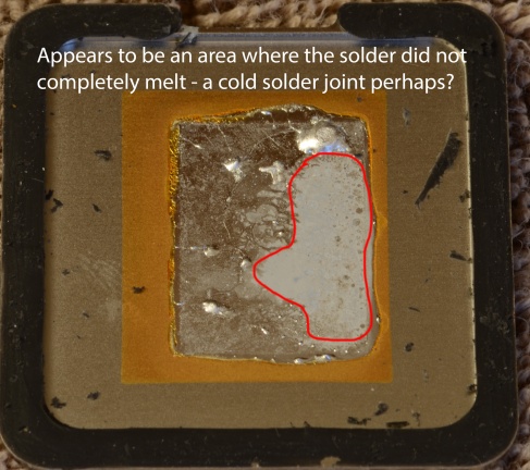
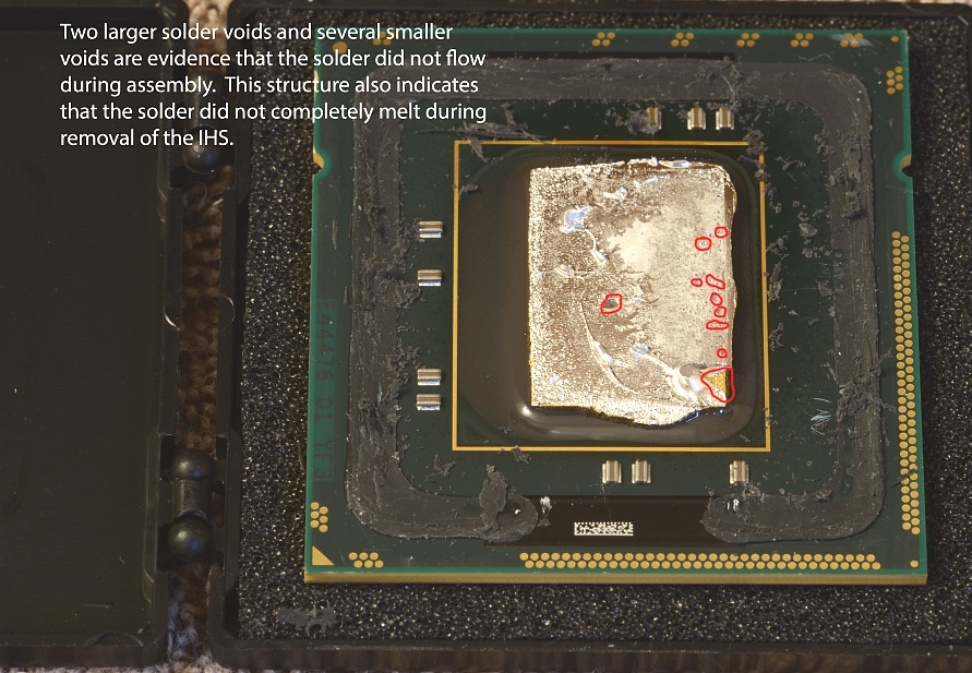
Poor soldering by Intel.
Removal of excess solder and adhesive remains:
The next task was to learn how to remove the excess solder on the CPU and the remaining adhesive from the printed circuit board. I did not want to heat the solder on the CPU with a solder iron as there is no way to know what temperature the CPU might be exposed to. Given that solder is very malleable, I decided to try using the razor blade to cut it away. This approach worked very well – only being careful to keep the blade flat against the CPU. You should not expect to see a clean gold-plated CPU at this point – a very thin layer of solder will not cause a problem in the final Mac Pro installation.
Cleaning the IHS adhesive off the printed circuit board was much more difficult. After another evening with Google, I found a video on YouTube where a Dremel tool had been used along with isopropyl alcohol. Given that the Dual Core Xeon was my test case, I elected to try this approach. I’m not convinced the alcohol is necessary as it does not soften the adhesive in the least – I elected not to use it on the W5590s. My only concern here was that static electricity could damage the CPU – to reduce that risk, I made certain that I was properly grounded with an electrostatic wrist strap. I would have no way of knowing if the processors were damaged until I had used this approach on the W5590s and installed them into the Mac Pro. I also changed the tool-head often in order to efficiently remove the material from all sides.
Post-removal inspection:
After removing the excess solder and the remaining IHS adhesive, I inspected the printed circuit board and CPU under a microscope. The inspection gave me confidence to proceed with this approach on the W5590s. The Dual Core Xeon board has only the CPU under the IHS – there are no other components. This is not the case with the Quad Core Xeon processors. As can be seen on the 2.26GHz CPU’s removed from the Early 2009 Mac Pro, there are 10 power supply bypass capacitors adjacent to the CPU. This made removing the IHS more difficult on the W5590s.
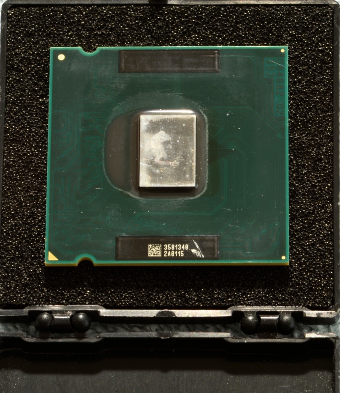
CPU with IHS, adhesive and solder removed.
Process with the Xeon W5590 CPU:
Using the approach documented here, I started work on the 3.33GHz Xeon CPU’s. All went well until the final inspection. At that point I noticed that one of the CPU’s had two damaged capacitors – I had cut into each of them while cutting the IHS adhesive. This problem was solved by purchasing a 2.26GHz Quad Core Xeon processor ( no IHS ) on eBay for $25 and using that as a donor to replace the damaged capacitors. There are 10 capacitors – each apparently 2.2 microfarads. I could have used the CPU’s that were in the Mac Pro, but I elected to keep those in case some issue came up with the W5590s when they were installed. A close visual inspection of the capacitors is important as damage there could result in the metallization layers shorting together.
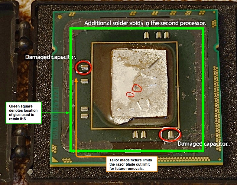
Damaged capacitors.
For future IHS removal projects, I have made a tailored jig to keep the razor blade flat with the printed circuit board. The design of the jig is such that a maximum depth of cut is maintained on all four sides, precluding damage to the surface mounted capacitors. The razor is held at an angle of 30 degrees between the two metal components with 0.260 inches of the blade extending into each channel – enough to cut the adhesive without damaging the capacitors.The fixture holds the razor blade rigid while the processor is moved, in the channel with the IHS side down, past the cutting edge. The fixture design allows the printed circuit board of the CPU to flex upward as the razor moves into the gap between the IHS and printed circuit board. (I have seen the engineering designs for Paul’s jig, and can confirm that it is exceptionally elegant. The accuracy of the tolerances suggests that there is no risk of damage to the CPU. – Ed).
If you want Paul to remove the IHS from your CPUs, you can email him in Cedar Rapids, Iowa, for more details, by clicking the icon below:
Click the icon to mail Paul Opsahl.
If you use his services, my benefit is precisely zero.
Thank you, Paul.
A note on temperatures. Intel’s web site states that TCase should be limited to 67C (153F to us Luddites); Paul explains that this refers to continuous use. TCase it the temperature on the outside of the IHS as Intel illustrates here:
TCase for the Intel Xeon W55xx CPU family.
How then can the CPU withstand the 165C (329F) required to melt the IHS solder? Well, Intel applies that level of heat when first attaching (however ineptly) the IHS, as that’s what is needed to melt the solder in the first place. Thus application of like heat when removing the IHS should not damage the CPU provided that the period is limited. Intel’s data sheets (doubtless much beloved of Chinese intellectual property thieves, though they still have to pay Novellus and Applied Materials for the costly fabrication machinery when copying/stealing Intel’s CPU designs) have data on tolerances which lead to this conclusion. Bottom line? Don’t overheat and don’t heat for too long and you will be OK. Just enough to melt the solder and permit removal of the IHS.
Best of all, have an expert like Paul do the work for you. His 2009 Dual Core Mac Pro uses de-lidded non-IHS W5590 3.33GHz CPUs, modified using his technique above, so you can be comfortable that he eats his own cooking.