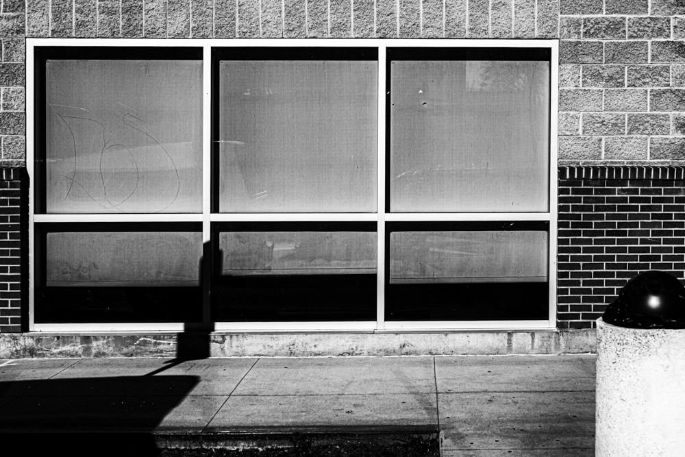
Or not ….

Leica M10, Light Lens Lab 50mm f/2 S-P II, 8x ND filter, covered to monochrome in NIK SilverEfex 8.
Or not ….
Leica M10, Light Lens Lab 50mm f/2 S-P II, 8x ND filter, covered to monochrome in NIK SilverEfex 8.
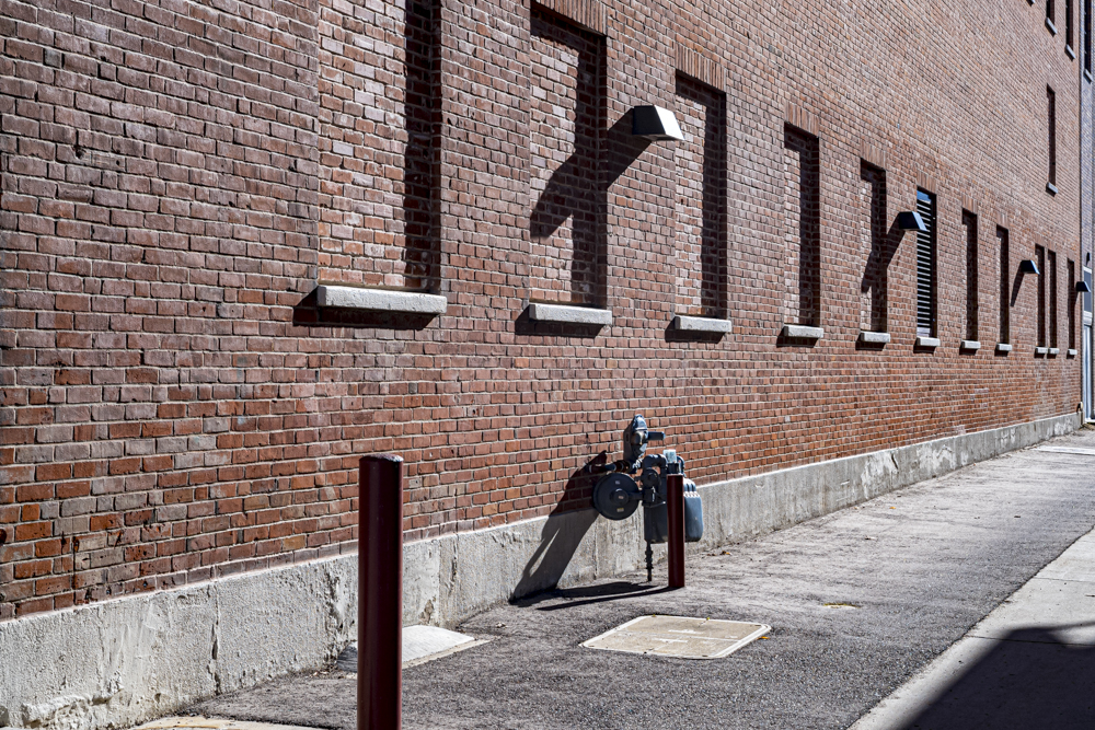
On the street.

Not the piano maker.

The Tardis.
Leica M10, 50mm f/2 Light Lens Lab S-P II, 8x ND filter. Both at f/2.
Making 6-bit codes permanent.
For an index of all Leica-related articles click here.
What are 6-bit codes?
Modern digital cameras with removable lenses communicate with the lens through a set of electrical connectors in the lens and in the camera body. This ensures that EXIF data – focal length, aperture, etc. – are sent to the digital image file, making cataloging and retrieval a simple process. However, lenses for Leica digital M body cameras have no electrical connections between lens and camera. Leica wants to keep things compact so instead concocted an ingenious optical communication system between the lens and the camera. An arc of 6 optical readers resides in the camera’s lens mount between the 4 and 5 o’clock positions, viewed from the front with the lens removed, and these optical sensors are matched with machined pits in the rear mount of the lens when the lens is mounted. Those pits are either filled with black ink (indicating a ‘1’ to the sensor) or filled with white ink (or not filled, remaining bare metal) pits, indicating a ‘0’. With six sensors the number of combinations is 2 to the power of 6, or 64. Hence ‘6-bit’. (There are actually up to 192 combinations as the fine technician Yukosteel explains here). This system permits communication of the lens’s focal length and design (Summicron, Elmar, Noctilux, etc.) to the camera which adjusts the sensor’s response to minimize optical aberrations. Current Leica optics come with the coding pits milled. Older ones and lenses from non-Leica manufacturers do not. But they can be added. Every digital M Leica, from the M8 on, uses this optical lens recognition system.
Why code the lens with 6-bit information?
As I depend on 6-bit coding to record the focal length of the lens used in EXIF data (a frequently searched field given my modus operandi in Lightroom), such coding is important to me. Further, proper coding of the lens results in the best possible optical performance, particularly with wider lenses and those which are prone to vignetting. Simply placing the ink codes on the plain rear flange of the lens is not a permanent solution as the ink will eventually wear away owing to friction between the flange and the camera’s lens mount each time the lens is inserted or removed. Once the ink wears away the lens will not be correctly recognized. So the long term solution is to machine the code pits on the lens’s mount or, if you are using Leica Thread Mount lenses, using an adapter with machined pits. With ‘pitted’ lenses, or LTM lenses with this type of adapter, the ink is protected from frictional wear over time.
Should you do this?
This is not a low risk procedure. I suggest you think carefully if you want to take the risk and rehearse the steps in advance. I found that practicing with a spare LTM-to-M bayonet adapter, illustrated below, made a significant difference to my level of confidence when it came to actually machining two of my lenses.
6-bit code table:
The table for more recent Leica lenses is here. The codes read clockwise looking at the rear flange of the lens. A ‘1’ indicates a black ink filled pit. A ‘0’ means do nothing. The correct ink is that in the Uni-Ball pen. A Sharpie does not work.
By the way, note the question marks against both versions of the Elmarit-M 135/2.8 lenses in the code table. They are there because, at least on my M10, a lens coded ‘001001’ is not correctly recognized, refusing to invoke ‘Auto’ recognition. So if you are coding a 135mm focal length lens, I recommend you use the code for the APO-Telyt-M 135/3.4 (‘110101’) which I can confirm works correctly. For my 135mm f/4 Elmar, a tack sharp lens which can be found inexpensively on the used market, I do not code the lens with ink, simply leaving the camera’s manual code set for the APO-Telyt-M 135/3.4. Thus when this sole uncoded lens in my collection is inserted it will be reported as a 135/3.4.
Which lenses are candidates for milling/machining?
DIY:
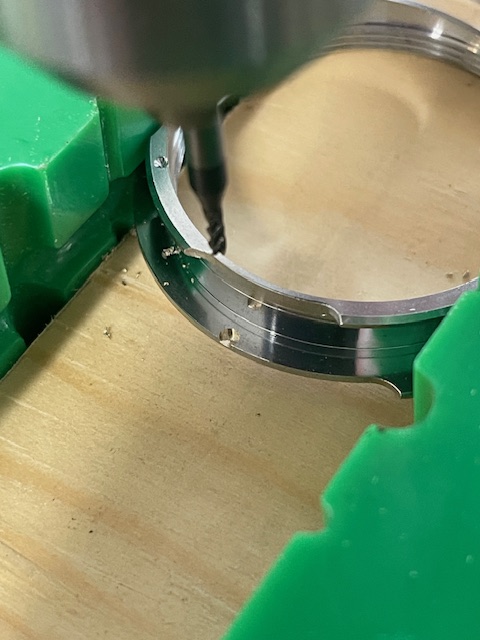
I got a quote of $350 from a respected Leica technician to engrave the code pits on the LLL lens (which he said he would have to dismantle before milling the coding pits), so I decided to do it myself, no dismantling involved. I procured a 1/16″ (0.0625″) diameter flat bottom mill bit – this is the correct size – and set about cutting the requisite code pits myself. The correct pit depth is a scant 0.01″, just enough to avoid abrasion of the ink fill. It’s not critical – you want it deep enough to hold coding ink below the plane surface of the rear flange.
No need to mill pits for ‘0’ locations:
There’s no need to mill pits for ‘0’ locations and given that each cut is an exercise in intestinal fortitude, the fewer cuts the better.
Oblong or circular pits?
Do the pits have to be oblong, like on Leica lenses? No. This is good news as machining an oblong pit is obviously more work/higher risk than simply machining a circular one. But there is a right and a wrong way to place the ink dot which will be used as the machining location if only a circular pit is being cut. Some experimentation disclosed that, with my M10 body, if the ink is toward the inside of the flange, nearest to the glass in the lens, it will not correctly register the lens automatically. If, on the other hand, the ink is toward the outside edge of the flange, furthest from the glass, it works fine.
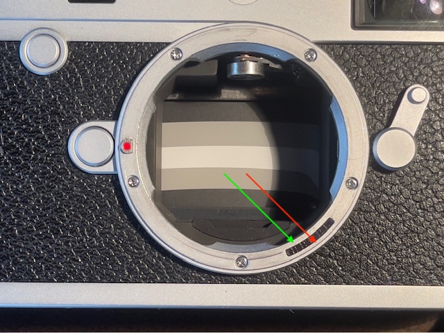
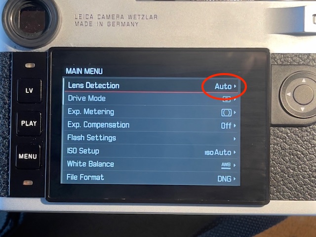
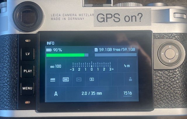
I suggest you check on your particular body before doing any machining by placing a single dot of ink (not an oblong), with the coding template in place, toward the outside end of the oblong cut-out in the template, let the ink dry and see if the lens is correctly recognized automatically. You do this by going to Main Menu->Lens Detection on the rear LCD display. You want the LCD to show the word ‘Auto’. See below. If it does not your ink needs to be relocated nearer to the glass. Do this ink dot placement process carefully and you will be assured of cutting the circular pit in the correct location.
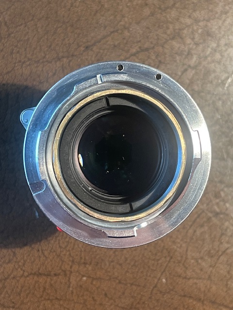
Pit placement:
The placement of the ink/milled cut toward the outside rim of the lens’s flange is visually obvious if you take a look at the lens mount on the camera’s body. As is clearly visible in the image below, the sensors below the glass arc are placed well towards the outside of the flange. Examine those through a magnifying glass and you will observe that the sensors reside behind square – not oblong – openings. Quite why Leica decided on oblong pits on the lens’s mount is a mystery when circular ones work just as well. Possibly this is a sample variation/tolerance issue? Given the high level of precision in the machining of both the mount and the lens’s flange that seems unlikely to me, but whatever.
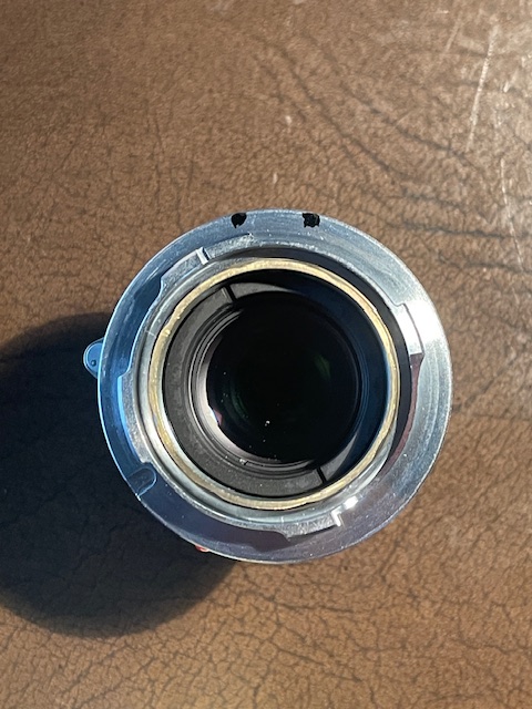
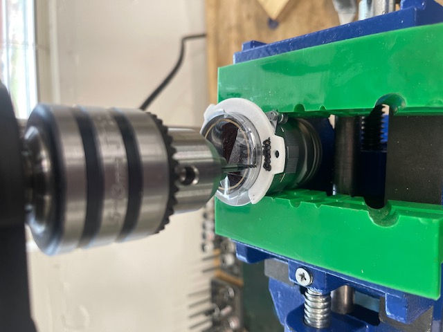
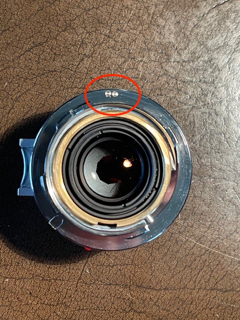
In the following image I have conferred circular (best as can be done with a felt tip pen) – not oblong – ink markings on the lens’s rear flange using the coding template and coding ‘100001’ for the 50mm f/2 Summicron lens. The circular ink marks have been placed towards the outside rim of the lens.
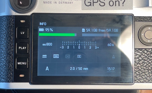
Confirmation of correct placement before milling:
Thus marked the lens is mounted and the LCD confirms that ‘Auto’ lens recognition is functioning, the lens being recorded as a 50mm f/2. This setting is visible at the bottom of the LCD display when the central button in the directional keypad is depressed.
Tools needed:
Total outlay? $190 and you will have a very handy drill press with a two axis vise when all is said and done. As the quote I received was for $700 for two lenses I can’t complain about the outlay for the DIY option.
Dry run:
I did several machining dry runs to get a feel for the milling cutter and for correct placement. I practiced on an old Leica LTM to M adapter. I found that placing the mill bit a thumbnail’s thickness from the edge of the flange was ideal – at first I milled too deep and too close to the edge leaving an ugly opening at the periphery of the flange.
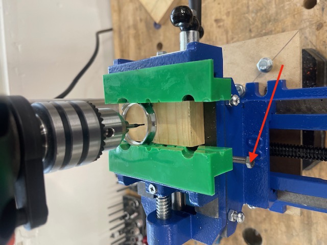
The order of events:
Here is the order of events after a trial run:
The above steps are illustrated below.
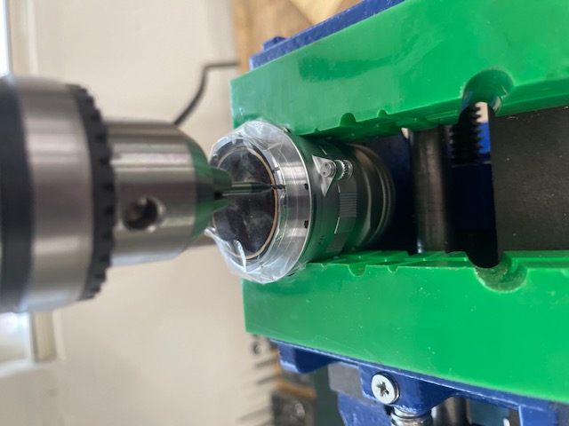
How deep to drill? Forget the depth stops on the drill press – they are an exercise in frustration. Just machine enough that you see brass showing through the chrome plating on the flange. You need only a very fine cut. If the lens’s mount is aluminum mill just enough that you can discern the pit.
Do the above and you will never have to worry about your ink codings wearing with use.
How to confer proper lens names in EXIF data:
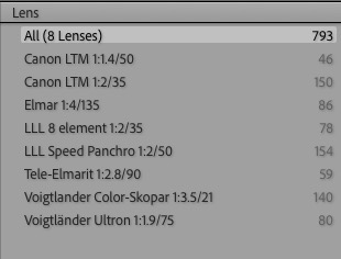
As coded the two LLL lenses are reported as “35mm f/2 Summicron” and “50mm f/2 Summicron” in EXIF metadata on import to Lightroom Classic. To properly name these as “LLL 8-element 1:2/35” and “LLL Speed Panchro 1:2/50” lenses in EXIF metadata I use the application described here. It takes mere seconds to do after each import of new images into Lightroom Classic. If I used multiple lenses for the latest import I filter metadata by focal length in LR Classic and apply the EXIF renaming tool for each batch of images with a common focal length. No reliance on memory is required.
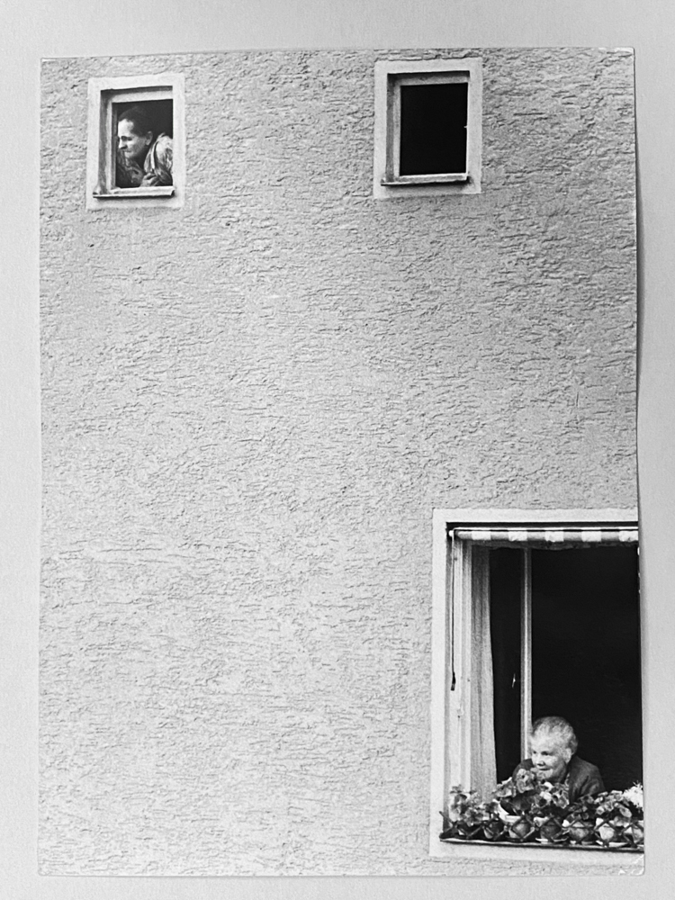
A fine German photographer.
Munich-based photographer Rolf Poss chanced on my 2008 piece on Ludwig Schricker, a little known German photographer with a fine eye for composition and a liking for expressionist images.
Rolf reports that the 1980/3 issue of Leica Fotografie magazine had a cover image by Schricker whom they described as “…. a judge in Straubing”. A true amateur.
Rolf generously shared many images from his collection with permission to reproduce them here.
Enjoy!
Winter sun.


Leica M10, 50mm f/2 Light Lens Lab S-P II, 8x ND filter.