Finally! Wide angle bliss.
I have been using the 20mm f/3.5 Ai-S Nikkor for a while now and it is both compact and optically excellent. But my first choice in a classic MF 20mm Nikkor was always the earlier UD of 1967. The snag is, it’s not easy to find a mint specimen.
The UD was a very special lens for its time. Until its creation, Nikon F owners made use of the mirror lock-up and separate optical finder needed to accommodate the 21mm design from Nikon’s rangefinder line. Hardly consonant with the SLR concept. Leica (with the 21mm Super Angulon for the original Leicaflex) and Zeiss (with the 21mm Biogon for the fabulous Contarex) adopted like strategies, mirror lock-up and all. All three came with the most awful, distorting viewfinders imaginable.
But the UD applied Nikon’s retrofocus research and resulted in a super-wide lens which needed no mirror lock-up or external finder. You saw through the pentaprism finder what the film would record. And it was massive, compared to their later 20mm designs – the 20mm f/4, f/3.5 and f/2.8, all MF and all excellent. Nikon lists the f/2.8 to this day.
So why bother spending all this time tracking down a pristine UD when all its successors are wonderful? Well, it’s that old fixation of mine. Metal. I believe lenses should be metal, not rubber or plastic mounted. I believe their ergonomics should fit the camera. And the D3x and D2x on which I use my lenses are very large bodies indeed. The 20mm Ai-S on the D3x is, frankly, rather dwarfed by the bulk of the body.
I searched some 18 months for a perfect UD specimen, being outbid several times on eBay as the UD seems to be attracting that vermin of the photography world, the gear collector. My sample, indistinguishable from new in every way, cost me $327 delivered, some $75 more than when I first started searching. By contrast, the Ai-S f/3.5 version can be had for maybe $250, or so. The CPU adds $30 and the Ai conversion requires a Dremel tool with a cut-off wheel, a small file and sweat equity.
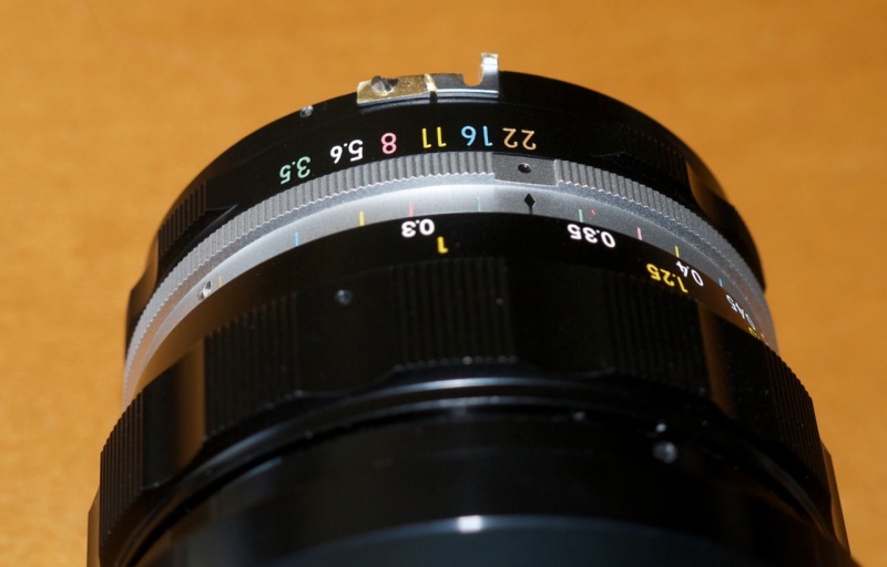
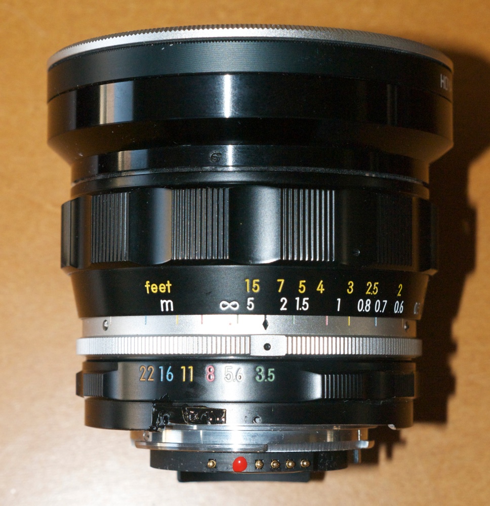
Here’s the real thing:
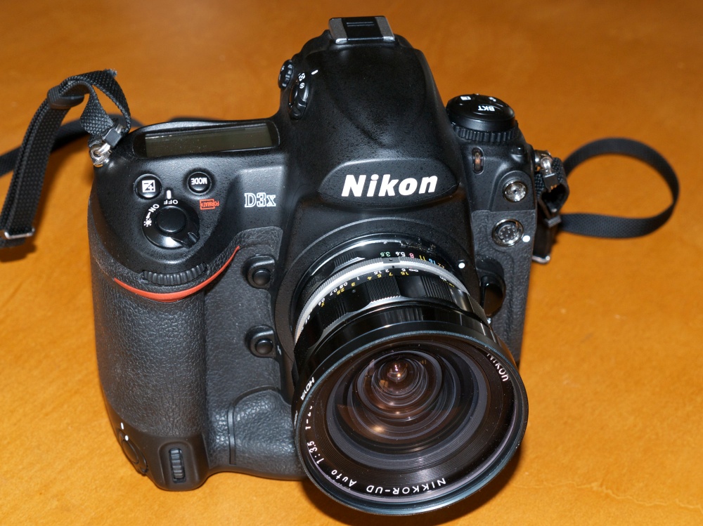
D3x, 20mm f/3.5 UD Nikkor. Mine was made in September, 1973.
Production ceased in April, 1974.
Nikon pulled no punches here. This lens is simply outstanding optically and mechanically. Almost 50 years after it was designed it remains a bedrock of solidity and pure old-fashioned mechanical engineering. Handling, feel, balance on the big body – there’s no comparison with its smaller and lighter successors. No play, no wobble, just high integrity build and finish. A man’s lens. For sheer beauty of execution only the pre-Ai 200mm f/4 Nikkor-Q compares.
My example was pre-Ai, as were all 20mm UD Nikkors, so it necessitated Ai conversion. Forget about trying to find genuine Nikon factory conversion kits – they are rarer than hen’s teeth.
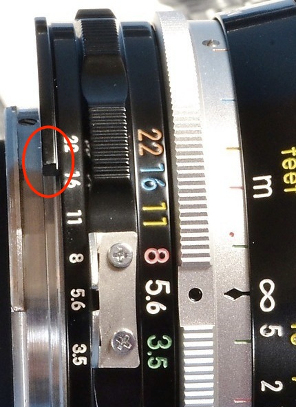
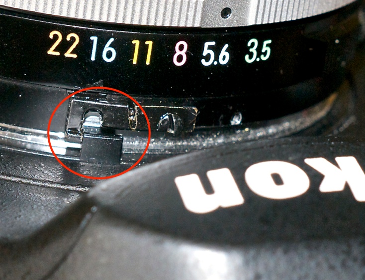
A factory modified UD Nikkor – note the protruding
ridge which abuts the aperture follower on the lens. Good
luck finding the modified aperture ring on the used market.
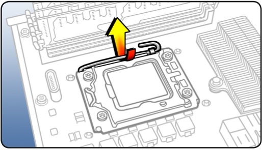
And conversion of this lens is tricky. Instead of just relieving the aperture ring to clear and activate the aperture follower on modern digital bodies, the lens has to have a protruding part attached to contact the follower, unlike other pre-Ai lenses. The easiest way to do this is to reverse the stock Nikon aperture claw, and cut off part of it until the dimensions are right. Nikon unwittingly provided just what’s needed for digital conversion, and the aperture claw I used has no purpose on modern Nikon DSLRs so its reuse has no negative effects. The modified, cut down claw will correctly contact the aperture follower as illustrated below.
The aperture follower. Very robust despite appearances,
the final thing is painted black to match the lens.
The aperture follower in use on the Nikon DSLR body.
Note the vacant claw retaining threaded hole to the right.
A note on ‘de-clawing’ the lens: Ordinarily, once I have converted an MF Nikkor to work on the modern Nikon DSLR, I remove the aperture claw on top of the aperture ring and store it. Because the two retaining screws are small and easily lost, I replace them in the vacant holes in the aperture ring, using a magentized screwdriver (any other way invites insanity). Do not replace the second claw retaining screw in the 20mm UD Nikkor (the other screw is used to retain the reversed claw). Doing so you will find that the screw countersinks too deeply into the innards of the lens and will prevent movement of the aperture ring.
The contrast in size with the later 20mm f/3.5 is striking:
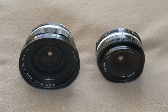
The 1967 design pre-Ai UD and the 1977 design Ai-S.
No rubber or plastic on the UD.
The handling of the big UD on the large D3x and D2x bodies is ergonomic perfection.
How about resolution? At normal enlargement ratios neither lens will let you down in big prints. But the optical design philosophies could scarcely be more different. The UD is computed for maximum resolution at the center and hang the edges. Indeed, central resolution remains largely unchanged, and outstanding, at all apertures, being pretty much perfect by f/4.5. By contrast the Ai-S optic compromises central resolution, trading it for more even across-the-frame performance. The Ai-S never quite matches the UD in the center and the UD never quite matches the Ai-S in the corners. For reference, I have a 48″ x 36″ print made from a 20mm Ai-S image and it’s perfect at normal viewing distances, so it’s not as if any excuses need be made for the compact Ai-S variant of this lens.
Here are center comparisons at f/3.5 and f/8, UD on the left. I’m using my usual utility pole in the backyard, that exemplar of America’s infrastructure. The equivalent print sizes would be 40″ x 27″, something very few users will ever make, so if you think the UD’s edges are poor and the Ai-S’s center is so-so, bear in mind what you are looking at:
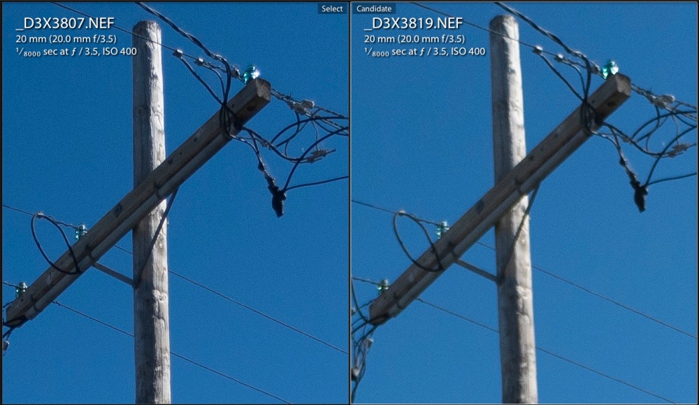
Centers at f/3.5.
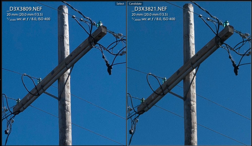
Centers at f/8.
And here are the extreme corners:
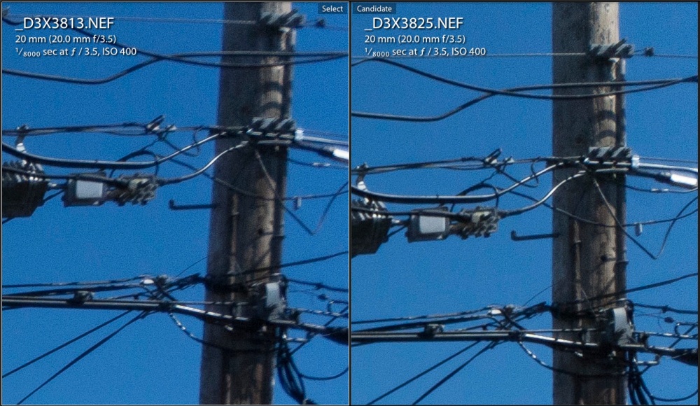
Corners at f/3.5.
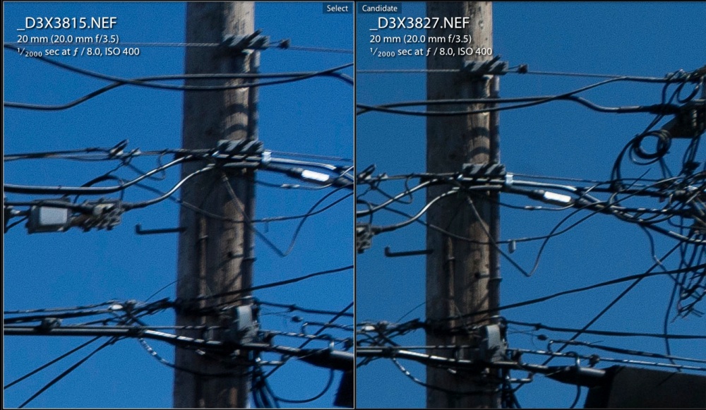
Corners at f/8.
I’ll trade central resolution for corner sharpness any day.
I used the same lens correction profile for the UD as for the Ai-S, after adding a CPU in the usual way. Comparison with the Ai-S showed almost exactly the same level of vignetting and optical errors, meaning wave/mustache distortion of straight lines at the edge. Both lenses cease vignetting by f/5.6.
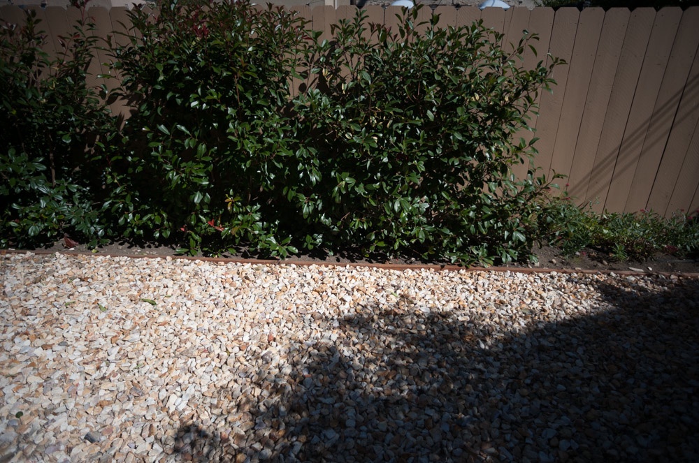
UD at f/3.5 – no profile. Note wave form distortion
of top of fence and vignetting.
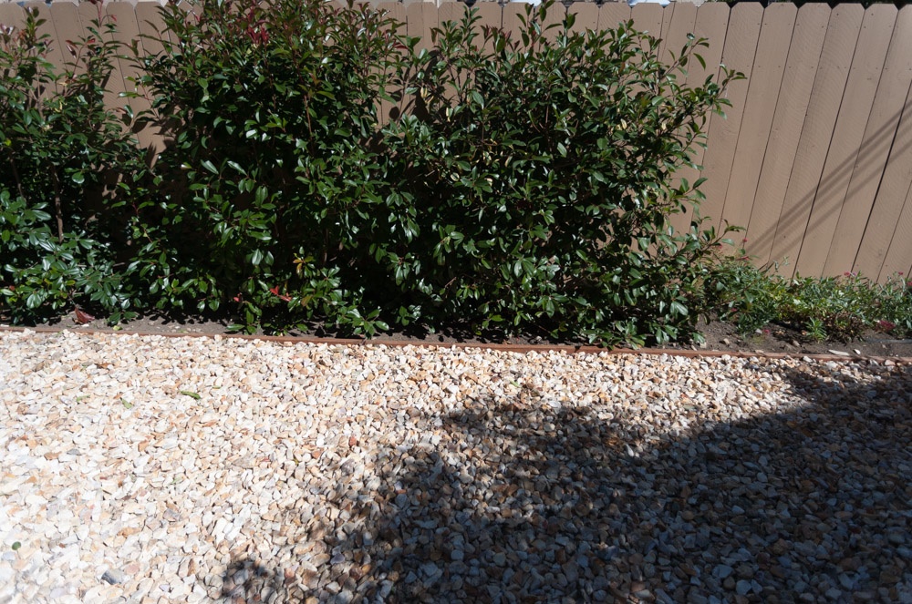
UD at f/3.5 with profile.
You can find the lens correction profile here and use of this profile corrects vignetting and renders straight lines straight, not wavy. Flare into the sun is almost identical, the Ai-S reproducing sharper magenta spots where the UD delivers one considerably smaller one, this despite the huge front element in the UD. In both cases flare spots are far less pronounced through f/5.6, becoming pretty objectionable by f/22 with the Ai-S, though easily corrected in post-processing. Contrast of the two lenses appears identical at all apertures.

The profile in use – Lightroom 5.
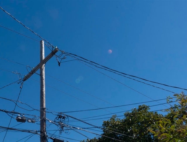
UD flare at f/22.
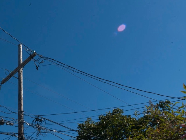
Ai-S flare at f/22.
The sun was just out of the frame in both images and no lens hoods were used. Both lenses have UV protective filters, which probably does not help matters. The UD is single coated, the Ai-S multicoated. The UD only shows a minor loss in definition from diffraction at f/22 – remarkable. To put this further in perspective, the UD is 1-2 stops sharper across the frame then the current 16-35mm AFS G zoom, which costs $1,300. So much for optical progress ….
If you have a big body Nikon and yearn for the days of mechanical engineering which Nikon has never surpassed, the 1967-74 UD Nikkor is for you.
The finished job. The red dot on the CPU serves as an alignment aid when mounting the lens.
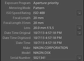
Correct EXIF data in LR5, read from the CPU.

Winston hammers away at his latest Lego kit. D3x, 20mm UD Nikkor at f/4.
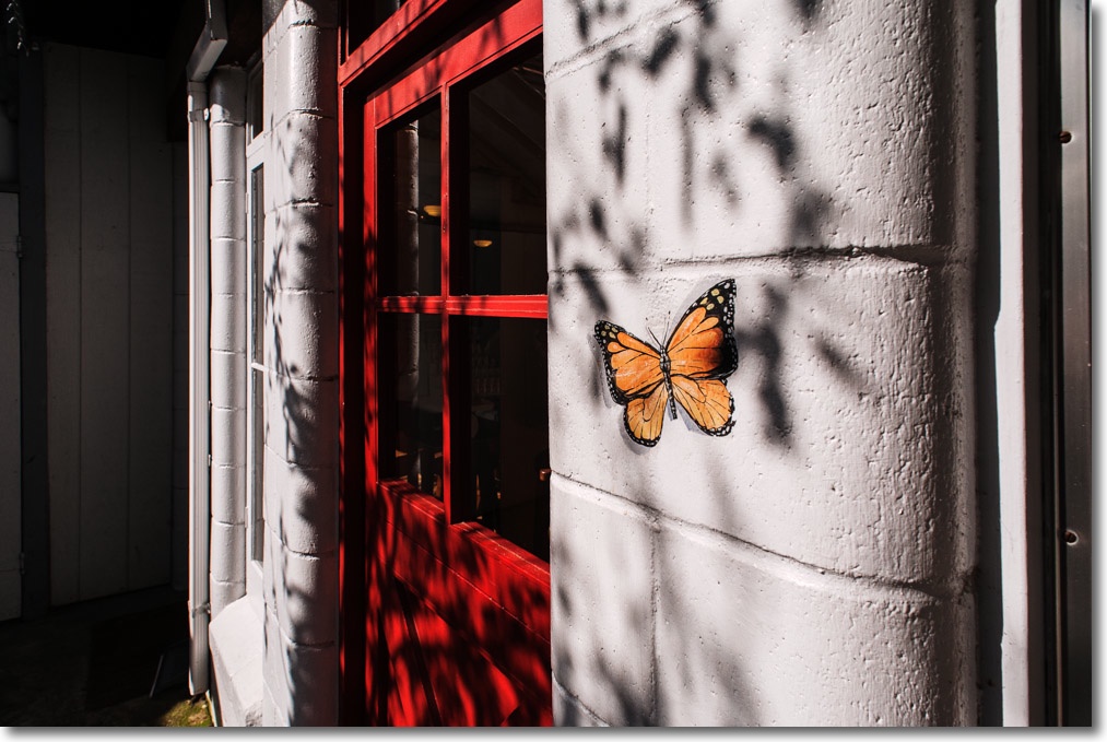
A few early snaps appear here.