Category Archives: Hardware

Stuff

The new Mac Pro – 2013 – Part XX

A poor value.

For an index of all my Mac Pro articles, click here.


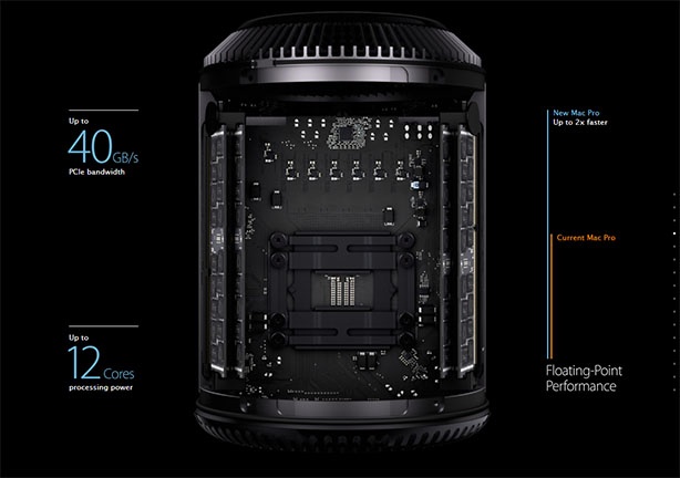
The new Mac Pro.

Apple announced some of the pricing for the new Mac Pro (“nMP”) yesterday and it’s hard to see much of interest for still photographers whose application use is centered on Photoshop and Lightroom, for the high price asked.

The base spec 4-core 3.7gHz machine comes with 12gB of memory and two AMD FirePro D300 GPUs for $3,000. The 6-core comes with 16gB of RAM and one 6-core 3.5gHz CPU with two FireCore D500 GPUs for $4,000. Each comes with one 256gB SSD. You will need to add external drive enclosures to those as there are no internal slots for drives, meaning USB3 (cheap) or Thunderbolt (still very expensive).

Given the CPU-intensive nature of PS and LR, the provision of two excellent GPUs in the nMP is largely wasted.

Compared with the 2.66gHz 4-core current MacPro (“MP”) the nMP 4-core will be 39% faster and the 6 core will be 97% faster on CPU tasks. However, you can buy a mint 2009 MP 4-core ($700) and upgrade it to a 6-core 3.33gHz i7-980 ($275 net of old CPU resale) with USB3 ($50) and a 256gB SATA III SSD ($175) on an Apricot PCIe card ($50) and with a GTX660 GPU ($150 net) for $1,400. I set forth the details of the upgrades here. The CPU speed of this upgraded MP machine will be 35% greater than the 4-core nMP and 10% less than the 6-core nMP and you will have a lot of money left in your pocket. And that’s before adding external disk storage for the nMP.

That makes the nMP a very poor value for still photographers. Movie makers should be able to take advantage of the new, dual GPUs when used with the latest version of Final Cut Pro X, but those GPUs are of little use to still snappers.

The 2009 4-core will only fall in value, owing to age and because more will become available as nMP early adopters sell their old machines. Thus the next few quarters will represent an excellent opportunity for 4-core MP buyers who, as a side benefit, will be spared all the usual teething troubles of a new, untested design, and will not need to buy external enclosures and costly Thunderbolt cables if that option is elected.

Update January, 2014:

Performance data are now coming out for the New Mac Pro and, frankly, they are very disappointing for the money asked. The $3,000 4-core base machine records a 64-bit Geekbench score of just 14,200. Compare that to the stock 2009 old Mac Pros:

  • 4-core – 9,100 (Used mint cost $750)
  • 4-core with Core i7/980 upgraded CPU – 15,000 ($1050) – faster than the nMP at one third the cost
  • 8-core – 12,000 ($1100)
  • 12-core with W5660 upgraded CPU – 25,000 ($1400)

Nor is video performance much to get excited about. With the single exception of Final Cut ProX, version 10.1 (not 10.0) no apps currently out there appear to use all the cores of the high-core count nMP fully, and with the better specified nMPs running $4,000 (6-core), $5,500 (8-core) and an eye-popping $7,000 (12-core) that’s simply money poorly spent until applications start using the new technology fully. Don’t hold your breath for Adobe to get with the action any time soon when it comes to PS and LR.

Finally, I am sick and tired of the puerlie images comparing the sizes of the small nMP with the older MP’s case. That’s comparing apples and oranges. If the old MP is a truck, then the new MP is a passenger car needing a bolt-on trailer. The old MP has storage for up to 10*** (or more) drives inside (with PCIe cards and optical drive installations in addition to the stock slots) whereas the nMP accommodates but the one PCIe SSD. By the time you have the nMP in a like configuration, you will have boxes and cable clutter all over your work space. And there are still no proper thermal stress tests of the nMP running under full load, an area where the old MP is a known and robust performer.

In conclusion, a stock or modestly upgraded 2009 old MP remains a superb bargain which yields little in performance to the new machine. A state-of-the-art nVidia GTX680 GPU ‘Made for Mac’ card can be installed in a couple of minutes in the old Mac Pro for some $500, providing video performance comparable to the nMP, so the buyer of the upgraded 8-core/W5590 old Mac Pro is looking at a bill of $2,000 with the fast CPUs and the better GPU. No contest.

Old MP buyers will only be winners over the next few quarters as early upgraders flood the used market with the older machines, making for abundant supply and falling prices.

*** Old MP drive capacity:

  • Four 2.5″/3.5″ in the backplane slots/trays. Up to 16TB total.
  • Two 2.5″/3.5″ in the optical drive area. Up to 8TB total.
  • Four 2.5″ in two dual Apricorn PCIe cards (cards are <$100 each). Up to 4TB total.
  • One or two more in the PCIe area attached to the sockets on the PCIe cards. Up to 8TB total.
  • Total? Up to 12 drives. Up to 36TB total.

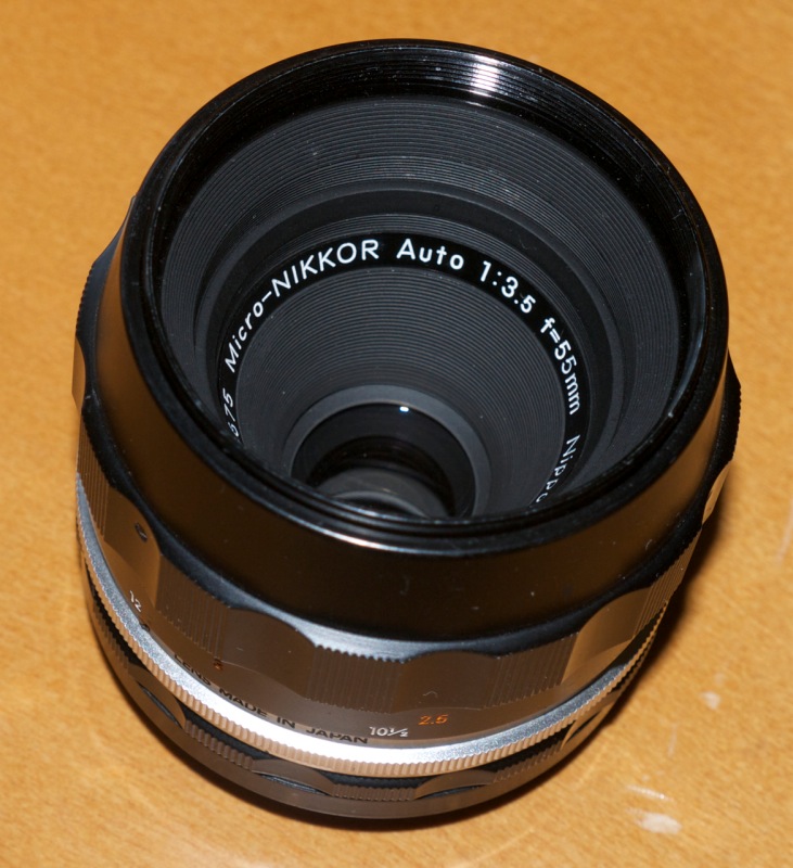
Nikkor 55mm f/3.5 Micro lens

A high definition macro lens.

Choices:

After the 50mm f/2 Nikkor, this is quite possibly one of the commonest Nikon lenses ever made. The 55mm f/3.5 Micro Nikkor is abundantly available in many variants:

  • Metal focus barrel, compensating aperture, pre-Ai
  • Metal focus barrel, non-compensating aperture, pre-Ai
  • Rubber focus barrel, pre-Ai
  • Rubber focus barrel, Ai
  • Rubber focus barrel, Ai, multi-coated

The later 55mm f/2.8 Ai-S MF optic is not recommended, owing to widespread reports of oil migrating from the focus mechanism to the aperture blades. Overhauling the lens to replace lubricants makes no economic sense owing to the high cost of labor. The even later 60mm f/2.8 versions, all AF, have the benefit of extending the focus range to life-size without the need to use an extension tube. But the construction quality of the 55mm f/3.5 was never equalled.

Ai conversion:

Spare no thought of destroying ‘collectible value’ by doing the Ai conversion. First, collectors are scum who serve only to drive up used gear costs. People who put gear in storage – be it camera or Ferrari – are beyond contempt in my book. Second, Nikon made hundreds of thousands of these lenses and you can always find any version in any condition on the used market, at very short notice. There is no such thing as a ‘collectible’ 55mm Micro Nikkor.


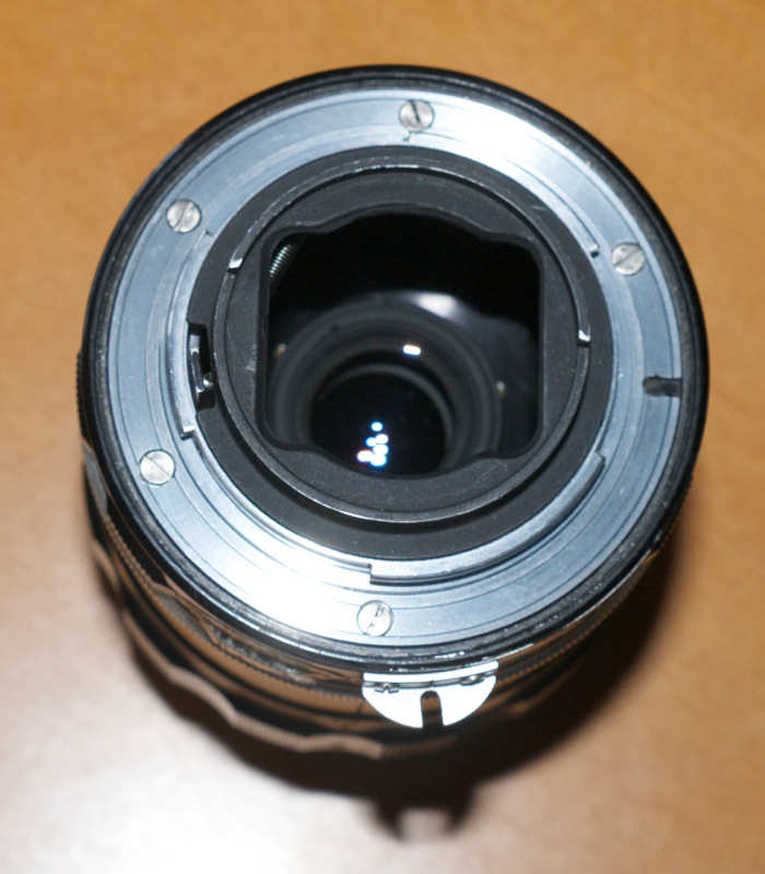
The rear of the lens is exceptionally well baffled.

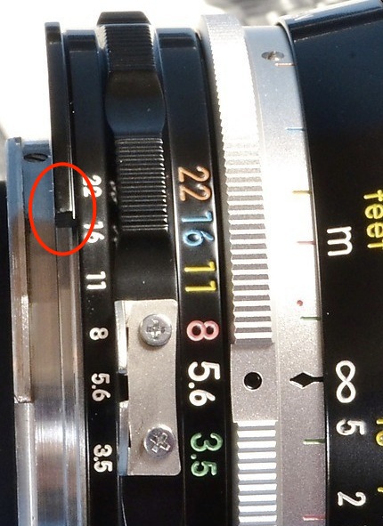
This means that the usual work will have to be done to file away an arc of alloy to permit clearance of and proper engagement with the aperture follower on the Nikon’s body. Not doing this will damage your camera. This work has yet to be done in the above illustration.

The snag is that the aperture collar where the filing has to be done cannot be removed by simply removing the bayonet flange – the five slotted screws shown. No, removing the small radial aperture ring indexing screw does not help. Don’t bother trying. So to work around this, after removing the bayonet flange, I placed some heavy-duty tape over the rear of the lens and scribed around carefully with a sharp knife to produce a thoroughly sealed interior which resisted any ingress of metal filings.


With the bayonet flange removed, 3M clear Scotch tape is placed in position, ready for filing.

Be sure to keep the lens focused at its closest distance – the protruding rear element will otherwise contact the adhesive tape, a move not calculated to enhance definition. Filing can now proceed in the usual way, using my guide here. All filings are blasted away with compressed air after which the Scotch tape can be discarded and the bayonet flange replaced.

CPU installation is as easy as it gets. No changes are needed, the CPU simply being glued in place in the usual way as I indicate here.

In use:


Deeply recessed front element.

The front element of the Micro Nikkor is deeply recessed within the barrel, so it’s unlikely that adding a lens hood will make any difference to results. Some reports indicate that the Micro Nikkor has poor performance at infinity, only really coming into its own at 1:10 and greater reproduction ratios. I have no idea where these urban myths were perpetrated – perhaps the results of a bad sample or two? – but mine is tack sharp at all apertures and subject distances, with optimum resolution being at f/5.6 through f/11 in the center and f/8 through f/11 in the extreme corners. Minor diffraction resolution losses become apparent at f/16 and f/22, and by f/32 these are noticeable, so I would avoid using the smallest aperture.

I do not recommend using a protective UV filter. It will serve only to attract light reflections, especially as it will be situated a considerable distance from the front element.

The lens is very light and the focusing helicoid exceptionally well designed, so that there is no play in the barrel even with the lens fully extended at its closest focus distance.

f/3.5 is not especially fast so how is focusing? I use the focus confirmation display in the D3x and hitting the illuminated central LED is very sensitive, meaning focus is very accurate. The infinity setting is exceptional, as the combination of 55mm Micro Nikkor and D3x body can easily distinguish between 250 feet and infinity. For reference, the same focus module is used in the D700, D3 and D3s bodies. So even at close focus distances, getting critical focus is trivial, though a tripod is strongly recommended in the close-up range where even minor movement of the camera can significantly upset focus.

Lens correction profile:

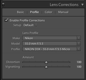
The lens is pretty close to perfect as is. There is very minor vignetting at f/3.5, and very low barrel distortion at all apertures. Chromatic aberration is almost non-existent. Nonetheless, I have made a lens correction profile which you can download here. This corrects these very minor aberrations, and if you add a CPU then you can have this profile automatically invoked and applied in Lightroom or Photoshop when downloading images from your camera’s storage card.


A CPU allows the correct profile to be automatically
loaded in Lightroom and Photoshop.

Comparison with the 50mm f/1.4 Nikkor:

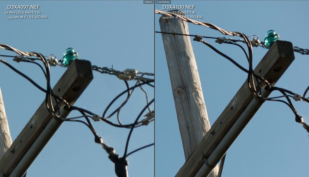
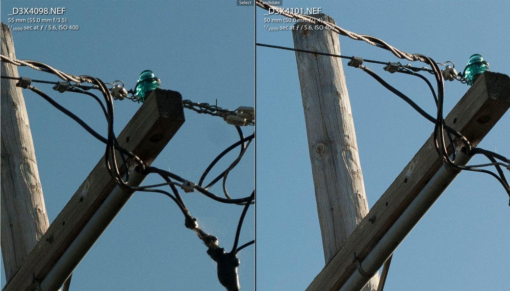
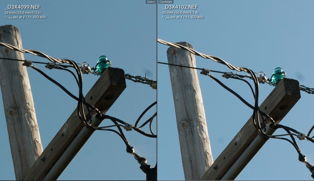
The 50mm f/1.4 Nikkor of the same era is a firm favorite of mine and both optics are absolute classics from the period when Nikon’s mechanical and optical designs peaked. It’s hard to put in words the tactile pleasure of using these lenses. How do they compare? At f/3.5, f/5.6 and f/8 the Micro Nikkor has the edge in errr…. edge performance, but you would need to make a 40″ print to prove it. The 50mm of course opens up to F/1.4 and the Micro Nikkor goes down to 50% life-size, so it’s horses for courses. Neither will let you down.

The following images are of a 27x enlargement of the top right corner of the frame:

At 1:2 closest focus distance:

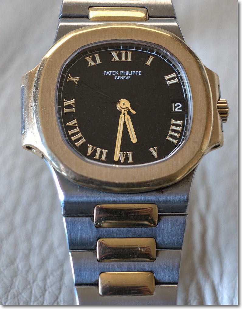
This image of a wristwatch was exposed at f/3.5, full aperture, at the closest focus distance:


Helicon Focus focus stacking of 14 images.


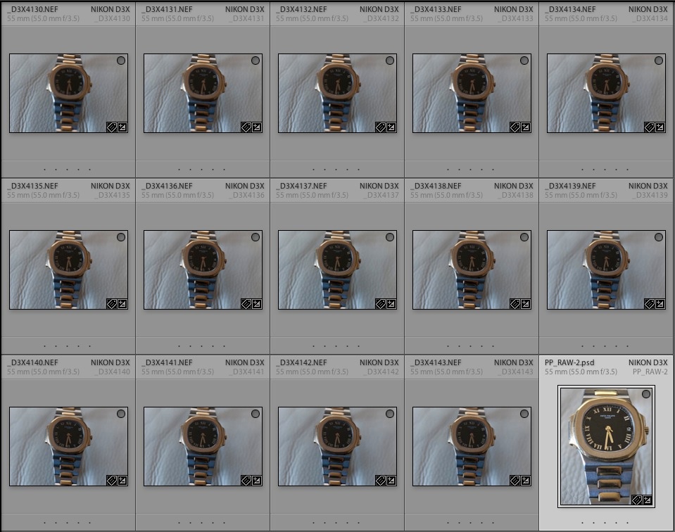
The 14 differentially focused images and the Helicon composite.

This gives you a sense of the maximum image size at the 1:2 closest focus distance. The image was created using Helicon Focus focus stacking software, and is a composite of no fewer than 14 differentially focused images, all taken at f/3.5. Because it takes a few seconds to take all the constituent images, refocusing a bit between each, I have removed the blur of the seconds hand using Photoshop.

The 55mm Micro Nikkor is recommended without reservation and at current market prices it’s almost offensively inexpensive.

Nikkor 20mm f/3.5 UD lens

Finally! Wide angle bliss.

I have been using the 20mm f/3.5 Ai-S Nikkor for a while now and it is both compact and optically excellent. But my first choice in a classic MF 20mm Nikkor was always the earlier UD of 1967. The snag is, it’s not easy to find a mint specimen.

The UD was a very special lens for its time. Until its creation, Nikon F owners made use of the mirror lock-up and separate optical finder needed to accommodate the 21mm design from Nikon’s rangefinder line. Hardly consonant with the SLR concept. Leica (with the 21mm Super Angulon for the original Leicaflex) and Zeiss (with the 21mm Biogon for the fabulous Contarex) adopted like strategies, mirror lock-up and all. All three came with the most awful, distorting viewfinders imaginable.

But the UD applied Nikon’s retrofocus research and resulted in a super-wide lens which needed no mirror lock-up or external finder. You saw through the pentaprism finder what the film would record. And it was massive, compared to their later 20mm designs – the 20mm f/4, f/3.5 and f/2.8, all MF and all excellent. Nikon lists the f/2.8 to this day.

So why bother spending all this time tracking down a pristine UD when all its successors are wonderful? Well, it’s that old fixation of mine. Metal. I believe lenses should be metal, not rubber or plastic mounted. I believe their ergonomics should fit the camera. And the D3x and D2x on which I use my lenses are very large bodies indeed. The 20mm Ai-S on the D3x is, frankly, rather dwarfed by the bulk of the body.

I searched some 18 months for a perfect UD specimen, being outbid several times on eBay as the UD seems to be attracting that vermin of the photography world, the gear collector. My sample, indistinguishable from new in every way, cost me $327 delivered, some $75 more than when I first started searching. By contrast, the Ai-S f/3.5 version can be had for maybe $250, or so. The CPU adds $30 and the Ai conversion requires a Dremel tool with a cut-off wheel, a small file and sweat equity.

Here’s the real thing:


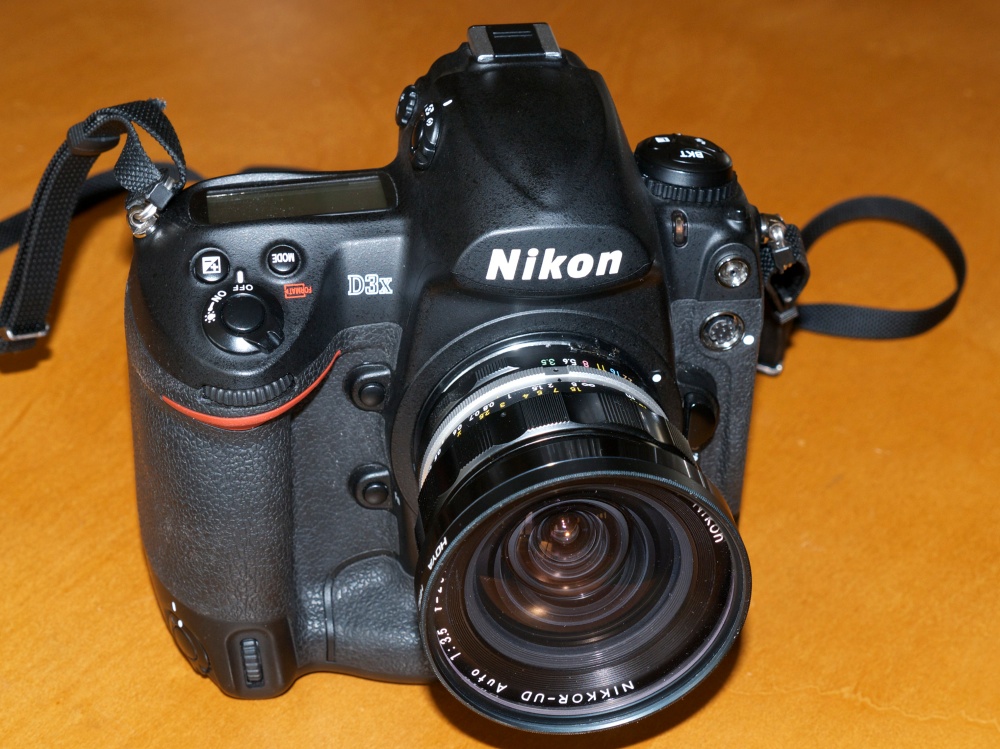
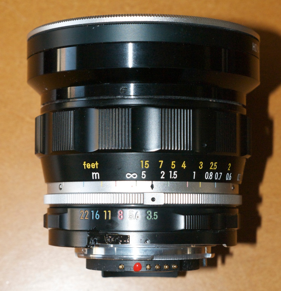
D3x, 20mm f/3.5 UD Nikkor. Mine was made in September, 1973.
Production ceased in April, 1974.

Nikon pulled no punches here. This lens is simply outstanding optically and mechanically. Almost 50 years after it was designed it remains a bedrock of solidity and pure old-fashioned mechanical engineering. Handling, feel, balance on the big body – there’s no comparison with its smaller and lighter successors. No play, no wobble, just high integrity build and finish. A man’s lens. For sheer beauty of execution only the pre-Ai 200mm f/4 Nikkor-Q compares.

My example was pre-Ai, as were all 20mm UD Nikkors, so it necessitated Ai conversion. Forget about trying to find genuine Nikon factory conversion kits – they are rarer than hen’s teeth.


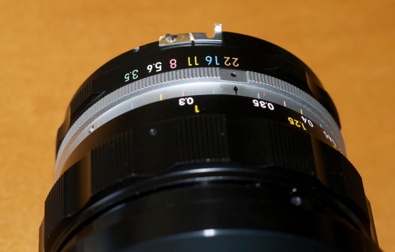
A factory modified UD Nikkor – note the protruding
ridge which abuts the aperture follower on the lens. Good
luck finding the modified aperture ring on the used market.

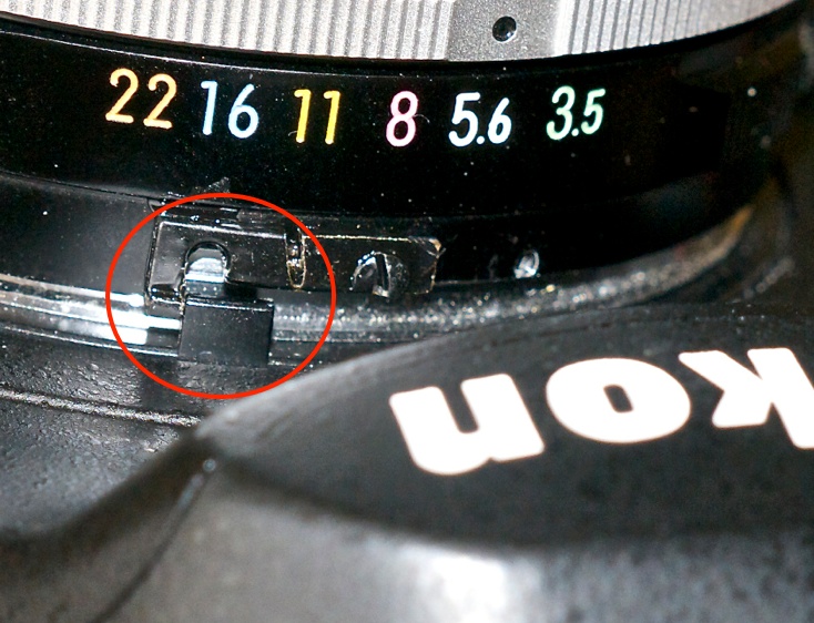
And conversion of this lens is tricky. Instead of just relieving the aperture ring to clear and activate the aperture follower on modern digital bodies, the lens has to have a protruding part attached to contact the follower, unlike other pre-Ai lenses. The easiest way to do this is to reverse the stock Nikon aperture claw, and cut off part of it until the dimensions are right. Nikon unwittingly provided just what’s needed for digital conversion, and the aperture claw I used has no purpose on modern Nikon DSLRs so its reuse has no negative effects. The modified, cut down claw will correctly contact the aperture follower as illustrated below.


The aperture follower. Very robust despite appearances,
the final thing is painted black to match the lens.


The aperture follower in use on the Nikon DSLR body.
Note the vacant claw retaining threaded hole to the right.

A note on ‘de-clawing’ the lens: Ordinarily, once I have converted an MF Nikkor to work on the modern Nikon DSLR, I remove the aperture claw on top of the aperture ring and store it. Because the two retaining screws are small and easily lost, I replace them in the vacant holes in the aperture ring, using a magentized screwdriver (any other way invites insanity). Do not replace the second claw retaining screw in the 20mm UD Nikkor (the other screw is used to retain the reversed claw). Doing so you will find that the screw countersinks too deeply into the innards of the lens and will prevent movement of the aperture ring.

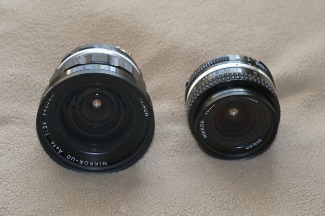
The contrast in size with the later 20mm f/3.5 is striking:


The 1967 design pre-Ai UD and the 1977 design Ai-S.
No rubber or plastic on the UD.

The handling of the big UD on the large D3x and D2x bodies is ergonomic perfection.

How about resolution? At normal enlargement ratios neither lens will let you down in big prints. But the optical design philosophies could scarcely be more different. The UD is computed for maximum resolution at the center and hang the edges. Indeed, central resolution remains largely unchanged, and outstanding, at all apertures, being pretty much perfect by f/4.5. By contrast the Ai-S optic compromises central resolution, trading it for more even across-the-frame performance. The Ai-S never quite matches the UD in the center and the UD never quite matches the Ai-S in the corners. For reference, I have a 48″ x 36″ print made from a 20mm Ai-S image and it’s perfect at normal viewing distances, so it’s not as if any excuses need be made for the compact Ai-S variant of this lens.

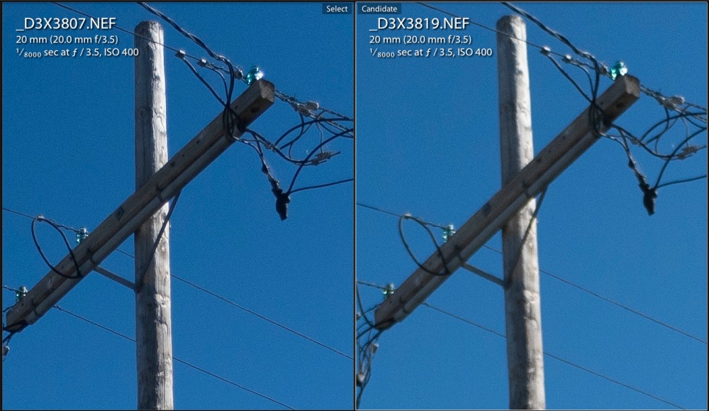
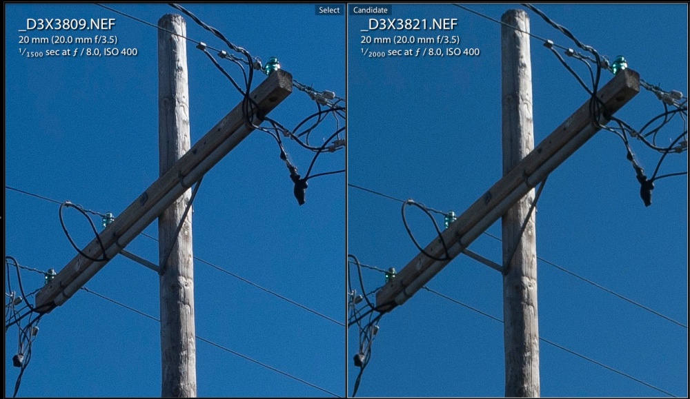
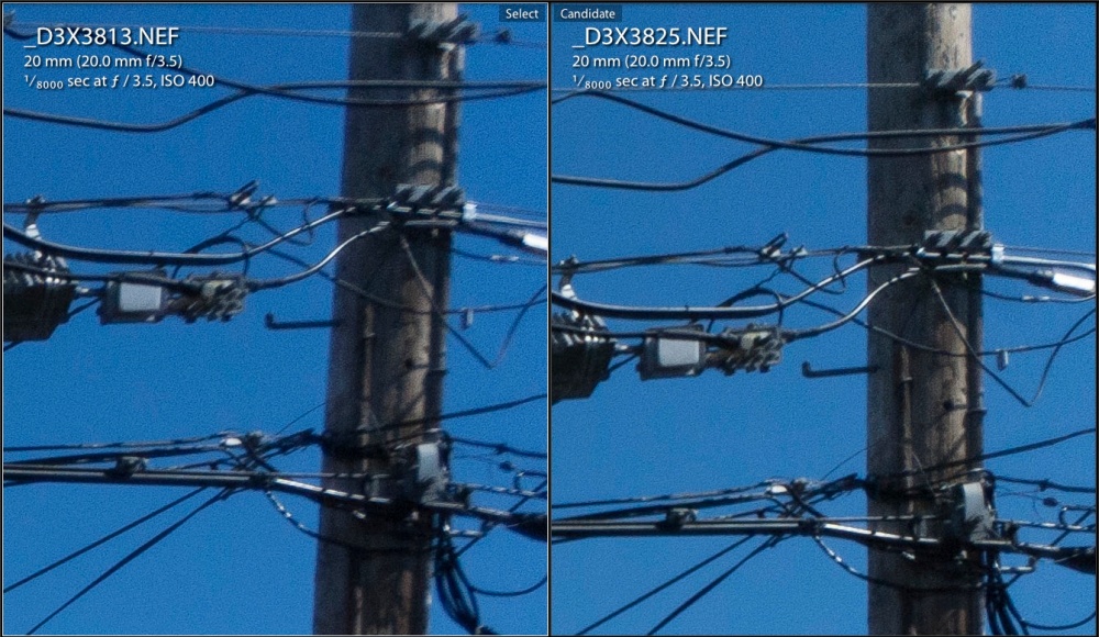
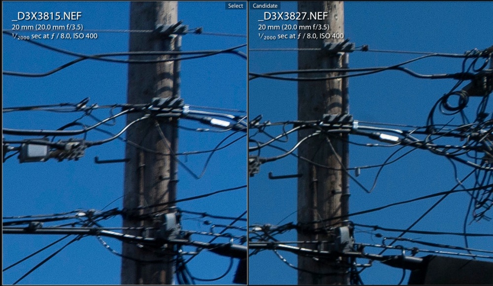
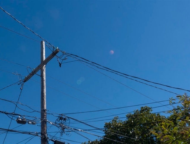
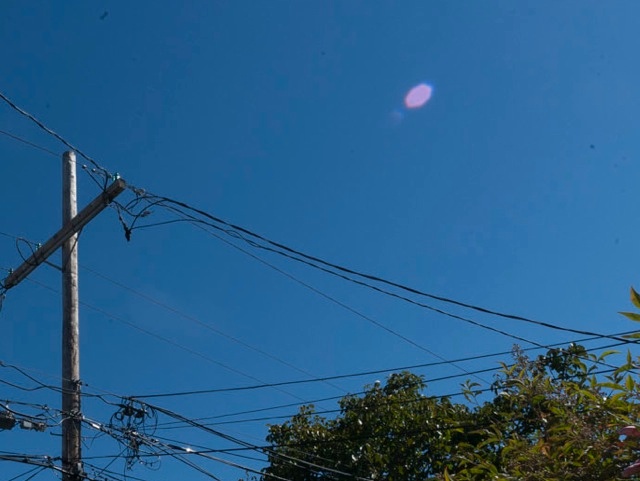
Here are center comparisons at f/3.5 and f/8, UD on the left. I’m using my usual utility pole in the backyard, that exemplar of America’s infrastructure. The equivalent print sizes would be 40″ x 27″, something very few users will ever make, so if you think the UD’s edges are poor and the Ai-S’s center is so-so, bear in mind what you are looking at:


Centers at f/3.5.


Centers at f/8.

And here are the extreme corners:


Corners at f/3.5.


Corners at f/8.

I’ll trade central resolution for corner sharpness any day.

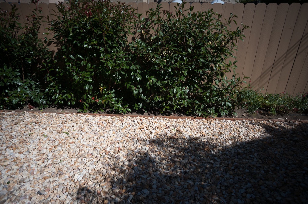
I used the same lens correction profile for the UD as for the Ai-S, after adding a CPU in the usual way. Comparison with the Ai-S showed almost exactly the same level of vignetting and optical errors, meaning wave/mustache distortion of straight lines at the edge. Both lenses cease vignetting by f/5.6.


UD at f/3.5 – no profile. Note wave form distortion
of top of fence and vignetting.


UD at f/3.5 with profile.

You can find the lens correction profile here and use of this profile corrects vignetting and renders straight lines straight, not wavy. Flare into the sun is almost identical, the Ai-S reproducing sharper magenta spots where the UD delivers one considerably smaller one, this despite the huge front element in the UD. In both cases flare spots are far less pronounced through f/5.6, becoming pretty objectionable by f/22 with the Ai-S, though easily corrected in post-processing. Contrast of the two lenses appears identical at all apertures.


The profile in use – Lightroom 5.


UD flare at f/22.


Ai-S flare at f/22.

The sun was just out of the frame in both images and no lens hoods were used. Both lenses have UV protective filters, which probably does not help matters. The UD is single coated, the Ai-S multicoated. The UD only shows a minor loss in definition from diffraction at f/22 – remarkable. To put this further in perspective, the UD is 1-2 stops sharper across the frame then the current 16-35mm AFS G zoom, which costs $1,300. So much for optical progress ….

If you have a big body Nikon and yearn for the days of mechanical engineering which Nikon has never surpassed, the 1967-74 UD Nikkor is for you.


The finished job. The red dot on the CPU serves as an alignment aid when mounting the lens.


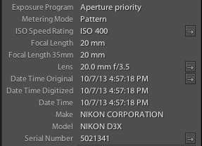
Correct EXIF data in LR5, read from the CPU.


Winston hammers away at his latest Lego kit. D3x, 20mm UD Nikkor at f/4.

A few early snaps appear here.

Mac Pro 2009 – Part XVIII

Doubling data storage.

For an index of all my Mac Pro articles, click here.

Preparatory work:

In an earlier article I illustrated how to install an Apricorn PCIe card which accepted a SATA III 250GB SSD to hold the OS, apps and the Lightroom catalog. The two existing 120GB SSDs were striped using RAID 0, and became the backup for the new 250GB SSD. Drive speeds and capacities doubled after this enhancement.

SATA III Hard Disk Drive:

A like approach applies to installing a larger data hard disk drive. The Apricorn card has one additional SATA III socket, permitting attachment of a large HDD, which has to be powered separately. My two data HDDs, each 1TB in capacity, are filling up, being 70% full. Spinning disk drives write data first to the periphery of the disk platters, gradually filling up toward the spindle. As rotational velocity drops as the spindle area is approached, data retrieval progressively slows as the disk fills up. So, at 70% full, I reckoned that it was time to do the same with the HDDs as I did earlier with the SSDs.

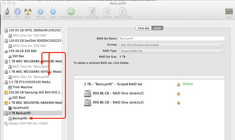
Thus I bought a Western Digital Red ‘server class’ SATA III 2TB HDD to serve as the primary data repository, with the two SATA II 1TB WD drives striped into one backup drive using Disk Utility and thus enjoying a doubling in backup speed. For details how to convert drives to RAID 0, refer to the earlier article.


The premium for these allegedly more robust drives over the standard Green and Black versions is a few dollars. Mine cost $105 plus tax. The warranty is three years, by which time these will have halved in price. Are these really more robust than plain vanilla drives? I have seen no data to prove it, but for a few dollars extra I’m not losing sleep over the hype. The estimable Tom’s Hardware site finds the Red to be a middling I/O performer but outstandingly cool and quiet, with low power consumption. That’s a trade-off I will take any day.

Power and data for the HDD:

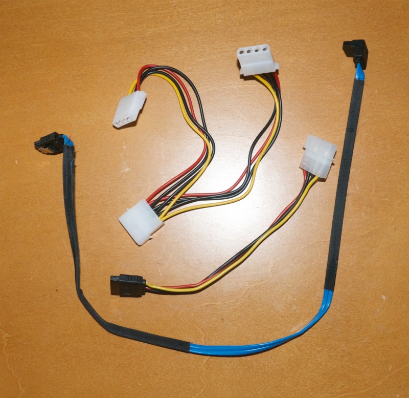
I had earlier installed a powered USB3 card, with power sourced from the optical disk drive area – click here for details. Thus, to power the new HDD all that was required was to split the power feed to the USB3 card using a Molex 1-to-2 Y cable, then a Molex to SATA power cable to energize the drive.


Cables – Molex splitter top, SATA power middle, SATA data bottom.

If you do not already have a powered USB3 card installed then power can be run directly from the spare unused connector in the optical drive area, the cable routed as I show in the USB3 article. The data connection is simply made with a SATA data cable connecting the spare port in the rear of the Apricorn SSD PCIe card with the data connector on the new HDD. The cable outlay is under $10.

Power use and supply limits:

Are the power supply limits of the PCIe slots being exceeded? No. The four slots can draw a maximum of 225 watts through the slots and an additional 2 x 37.5 watts from the two backplane connectors intended to power GPU cards. Here are the maximum PCIe power consumption data for my configuration:

  • nVidia GTX660 graphics card – 140 watts (37.5 from the backplane board, 102.5 from the PCIe slot).
  • Orico USB3 card – probably 10 watts
  • Apricorn PCIe card with 250GB SSD – 4 watts
  • WD Red 2TB HDD – 10 watts

So that’s a total power draw of 127 watts out of 225 watts available through the PCIe slots. That’s very conservative at 56% of capacity.

What is of greater concern is the use of top end GPU cards like the nVidia GTX780 and ATI/AMD HD 7950 and HD 7990.

  • GTX780 – 250 watts – 75 from the backplane board, 175 from PCIe – OVERLOAD!
  • HD 7950 – 200 watts – 75 from the backplane board, 125 from PCIe
  • HD 7990 – 375 watts – 75 from the backplane board, 300 from PCIe – OVERLOAD!

Meaning that if you use one or two of these cards and drive them hard (why else buy them?), you must use an auxiliary power supply, which can be located in the DVD drive cage.

However, if you accept that a card of the calibre of the GTX660 is as much as you will ever need for still image processing (it is), then power consumption is not a concern.

Placement of the HDD:

The final issue is where to store the new HDD, as all my regular SATA II ports are taken. One option is to store the HDD in the optical drive area, but that area is poorly cooled and not the best choice.

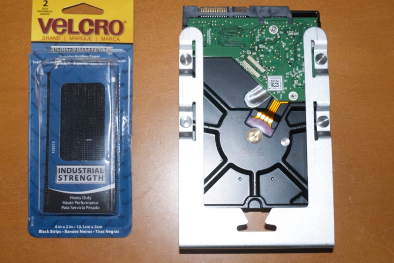
I opted to attach the HDD to the top of the PCIe fan case using Velcro. In this location the power and data cables are easily connected and there is ample cooling. Velcro makes removal of the HDD easy. Rather than attach the Velcro directly to the HDD – heat and Velcro adhesive do not make for long term stability – I attached the HDD to the spare disk drive sled which became available when I replaced one of the 3.5″ HDDs with a 2.5″ SDD. I used the OWC sled to attach the SSD instead.


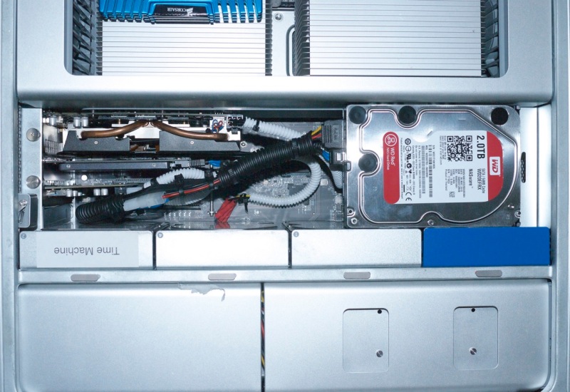
WD Red 2TB SATA III HDD installed in a stock Mac Pro drive sled.


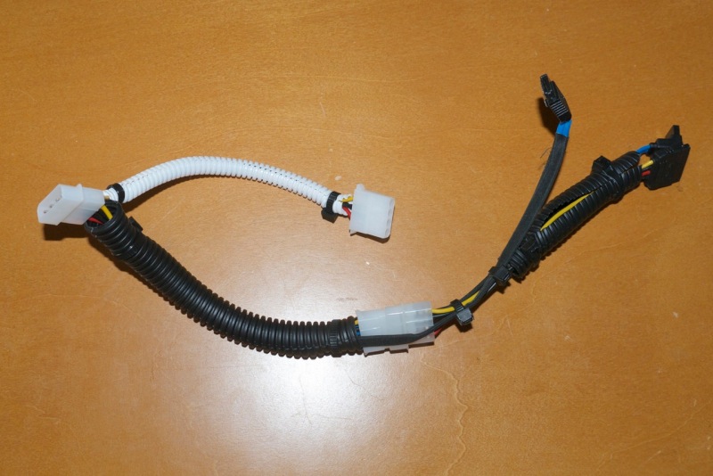
Cables neatly arranged with cable covers and tied into a harness.

The stock HDD sled is a perfect fit between the processor cage and the existing HDDs in their regular locations. I used industrial grade Velcro whose adhesive and hook-and-look surfaces make for very strong bonds and made sure to clean the mounting surfaces with a swipe of isopropyl alcohol to remove dirt and grease before attaching the Velcro.


Velcro in place on top of the PCIe fan housing.

Take double care with those ghastly Molex connectors. It’s common for a pin or socket to come loose and recede as the two are mated, making for a bad connection. Ask me how I know. If you find you have two in-line Molex male-female connectors, as here, I advocate cutting them off and crimping the wires using a crimping tool and crimp connectors. Superior in every way.


The installation completed.

Thereafter it’s a simple issue of moving data over, using Carbon Copy Cloner, from the existing 1TB data HDD to the new 2TB drive, and then using Disk Utility to make the two original 1TB drives into one 2TB RAID 0 drive, setting the latter up as the backup drive in CCC and cloning all data back from the new 2TB HDD to the RAID 0 2 x 1TB pair of HDDs. As usual, I am careful to recreate the daily scheduled CCC back up task from Data HDD to Data HDD Bak, as use of UUIDs for these disk dictates that step.


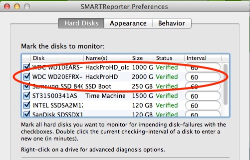
The new SATAIII HDD is correctly reported by the SMART disk utility.

Additional storage:

Need yet more storage? You can convert to 4TB HDDs. All that’s called for is money. They run around $200. Further, Seagate just announced a new storage technology known as Shingled Magnetic Recording which allows yet more data to be crammed into existing platters, starting at 5TB. You can bet we will see 8 or even 10TB per drive before long. Astounding! Rumors of the spinning HDD’s death are greatly exaggerated and brilliant electronics engineers are doing some very innovative work here.

The bottom line is that the Mac Pro owner wishing to have a minimum of external clutter and cabling can easily run internal storage up to 20TB at present, and much more down the road. That should keep most users happy, unless they work for the NSA. If yet more is needed, use external USB3 cases loaded with as many HDDs as you need, but for my more modest storage needs having everything inside the Mac Pro’s case is perfection. A CrashPlan cloud backup covers for earthquakes and fires at the Mac Pro’s location.

Measurements:

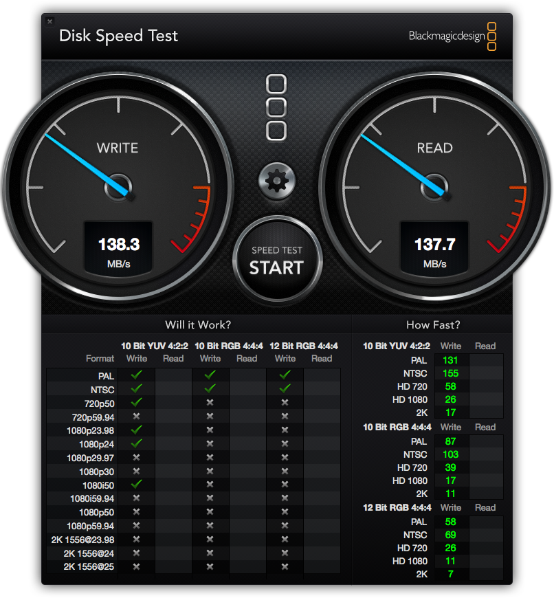
I illustrate drive Read and Write speeds below for the original 1TB SATA II HDD, the new SATA III WD 2TB Red and the two original 1TB HDDs striped into one HDD (as seen by Finder) using RAID 0.

A) Original 1TB 7200rpm HDD running at SATA II speed:


Original 1TB 7200rpm HDD running at SATA II speed.

B) New 2TB WD Red 5400-7200 variable rpm running at SATA III speed:


2TB WD Red 7200 rpm running at SATA III speed.

c) Original paired 2 x 1TB SATA II HDDs striped as one 2TB HDD in RAID 0 (WD Green 7200rpm) – outstanding performance with speeds tripled:


Paired 2 x 1TB SATA II HDDs striped as one 2TB HDD in RAID 0.

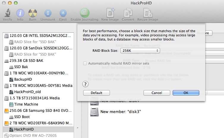
I opted for larger 256K block sizes when striping the two older 1TB drives, as most of the activity is writing large photo files:

Here is Disk Utility after creating the new 2TB striped set:

Sound levels:

Addition of the WD 2TB Red drive makes no change to noise measured at ear level, two feet distant from the Mac Pro on the floor. This remains at 42-43dB – a low level susurrus of white noise.

Temperatures:

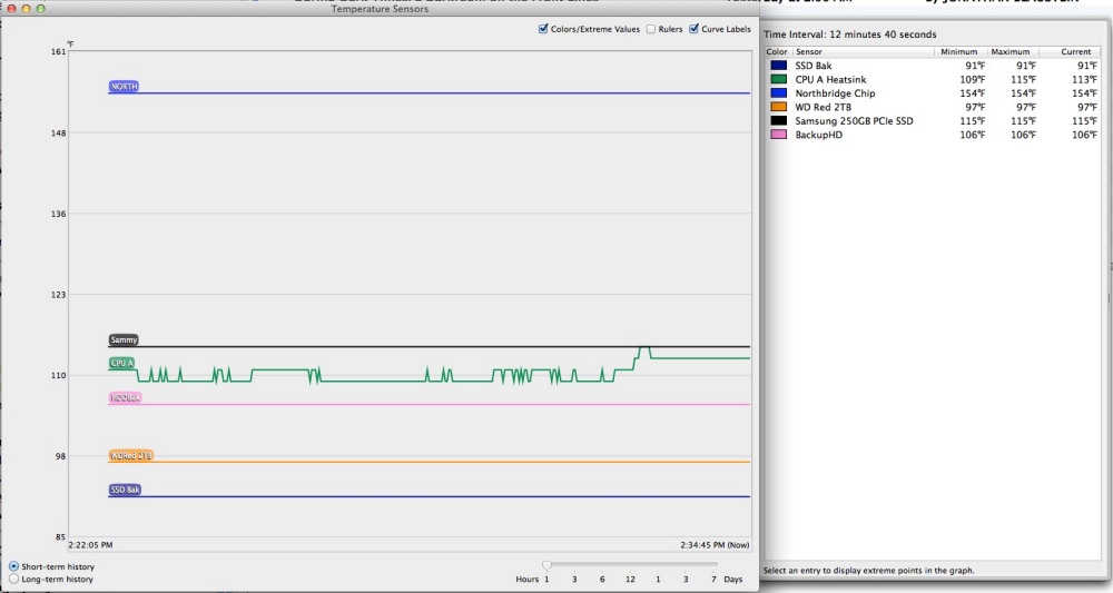
As you can see, the 2TB Western Digital Red SATAIII HDD runs very cool – it’s the orange trace, below. This temperature chart was run during the clone of the newly populated Red (‘WDRed2TB’) back to the newly created 2 x 1TB Raid 0 striped HDD pair (‘BackupHD’) – the pink trace. The Samsung 250GB PCIe SSD (‘Sammy’ – brown trace) runs warm, likely owing to its proximity to the Zotac nVidia GTX660 graphics card, which runs hot. The Northbridge chip – blue trace – runs warm by design, and remains 70F below its operating limit.

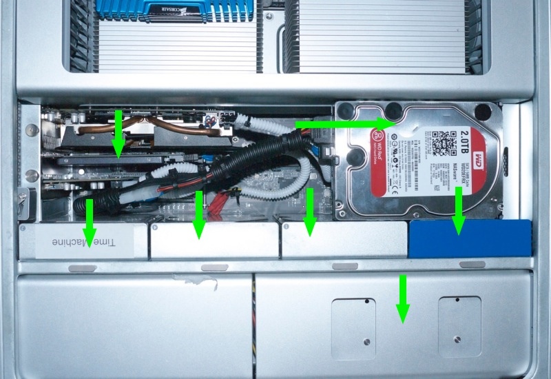
Spot the drives:

Green arrows designate drive locations.

The seventh is an SSD hidden in the optical drive cage, lower right.

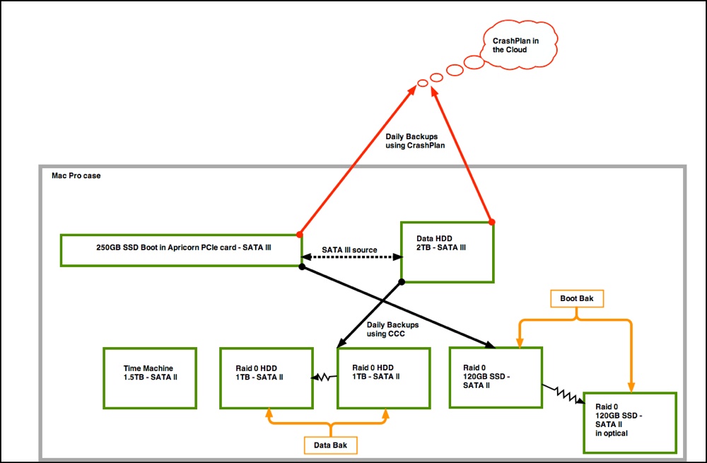
Here is the drive topology and back-up design:


Drives in the Mac Pro’s case and in the Cloud.


All drives are inside the case.

Replacing trashed grommets:

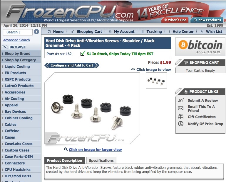
The soft rubber grey grommets in the Mac Pro’s drive sleds both help retain the drive screws and confer a modest level of vibration damping. They rot and disintegrate with age. You can buy replacements here – the cost is for a pack of four:


Replacement rubber disk drive grommets. Click the image to go to the site.

Mac Pro 2009 – Part XVII

Doing it right.

For an index of all my Mac Pro articles, click here.

If you examine the three model years and six versions of the current Mac Pro – 2009, 2010 and 2012 – each of which came in single or twin CPU models – only one of these uses a non-standard Intel Xeon CPU design. The odd duck is the 2009 dual CPU version which uses CPUs without the Integrated Heat Spreader (IHS), an alloy top plate which is both glued and soldered to the CPU and the surrounding base itself. I have read no definitive reasons for this approach and would guess that Apple must have been concerned about thermal performance, the no-IHS design likely being easier to cool with the massive heat sinks used in the Mac Pro. What is mystifying is that the 2010 and 2012 dual Mac Pros reverted to stock IHS CPUs with little or no other apparent changes, other than to the height of the heat sinks to accommodate the thicker CPUs and reversion to stock sprung CPU retainers.

You can see the difference in Apple’s own drawings in their service manuals:
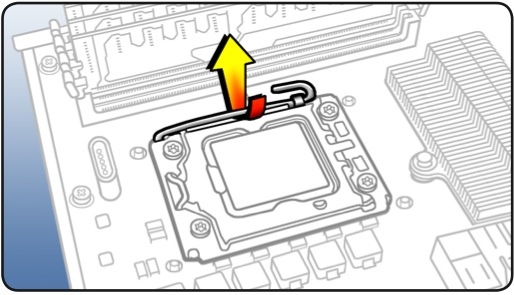

Single and twin CPU retainer in all except the 2009 dual models.
This is the standard sprung retainer used in most Intel CPU installations
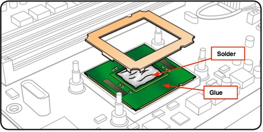

Dual CPU design in the 2009 8-core – no IHS.
My annotations refer to the IHS design,
showing how the IHS is attached.

The practical upshot of the dual CPU 2009 design difference is that upgrading the CPU means that the heat sinks must be raised 2mm, a process fraught with risk of damage to the relatively fragile CPU socket, if not to the CPU itself. A damaged socket means a new processor board, some $400, and loss of use while you wait for the replacement. That and a bruised ego, not to mention time wasted.

Additionally, revisions have to be made to the heat sink fan power connectors and additional thermal pad material must be installed on the voltage regulators to maintain proper thermal contact with the heat sinks. Finally, fresh threadlocker should be applied to the retaining bolts for the heat sinks, as I illustrate.

In mechanical tasks proper instructions never use the word ‘judgment’. Judgment is subjective. ‘Subjective’ translates, as often as not, to catastrophe. Thus, in determining a measured approach to CPU upgrades in the dual 2009 machine, I set forth a low risk, objective way of securing the heat sinks with the upgraded, thicker CPU in place which will protect those fragile CPU sockets from damage.

Yet, clearly, the most elegant way of doing the 2009 dual upgrade is to use upgraded CPUs without the IHS fitted. The snag is that Intel appears never to have marketed these. This has caused determined upgraders to use various methods to remove the IHS, including razor blades, unmanaged heat, force and abrasive means to emulate the stock Xeon E5520 design.

The advantages of this approach are that the upgraded CPU is simply dropped into the socket, the loose alloy frame is placed over the CPU and the heat sinks are reattached with exactly the same number of bolt turns as was required to remove them. No changes are needed to the temperature sensor sockets in the heat sink and no additional thermal pad material need be installed. Nice and simple.

The disadvantage is that the IHS removal process is high risk. The risk includes mechanical damage to the CPU and financial damage to your pocket-book if you get it wrong. And it is not easy.

Reader Paul Opsahl had purchased a 2009 dual CPU Mac Pro after seeing my series of articles on this exceptional bargain of a computer. When Paul mentioned that he had managed to remove the IHS plates in the two Xeon W5590s he used in his 2009 dual upgrade, I was all ears. I asked him to detail his method and I think you will find it makes for fascinating reading. As the IHS is both soldered and glued to the CPU and the printed circuit board, some razor blade work remains but Paul’s technique to remove the solder bond is obviously the right way to do this, and I present his work below.

You will find Paul’s approach rigorous and well researched – in marked contrast to the amateur hour methods found on the many chat boards out there. You will also be amazed at just how shoddy Intel’s soldering technique is – maybe reason enough for Apple to adopt a non-IHS design in the first place!

If you want to install upgraded non-IHS CPUs of your choice in a dual 2009 Mac Pro, and want do do it right with non-IHS CPUs, contact Paul and see if he can fit you in while doing his day job and keeping bread on the table. You will find his rates for the work of removing the IHS reasonable. Regard the payment you make to him as the cost of insurance against damaging the CPU sockets in the processor board of your precious Mac Pro. Paul is an electronics engineer, not a backyard hacker, and has the right tools for what is a difficult job.

Paul takes it from here.

* * * * *

Preliminary discovery:

I started with a visit to the local computer recycler (Midwest Computer Brokers) in Walford, IA. I asked if they had any old Xeon processors available – any speed. I explained that I wanted to learn how to successfully remove the IHS. They gave me a Pentium 4 processor that already had the IHS removed with the aid of a blow-torch and a flat blade screwdriver. I decided that I could use that in a first experiment to determine what temperature the solder melts at ( more on that later ).

During a second trip to MCBIA, I specifically asked for a Xeon processor with the IHS intact. They offered to sell me a known good Dual Core 3.03GHz Xeon for $40. The goal with that device was to learn how to cut through the adhesive without damaging the printed circuit board and remove the IHS using a temperature controlled heat plate. I had seen a post where someone had used a double-edge razor for this purpose. I opted for a single-edge razor thinking there would be less chance for me to see blood. The single-edge blade worked, but I later learned that the single-edge blades are almost twice as thick as the double-edge blades ( the double-edge blades I used later on the Quad Core Xeon processors are approximately 0.004 inches thick ). The adhesive is very soft, but tightly compressed between the IHS and the rigid printed circuit board in a gap of about 0.008 inches. That narrow gap means that it’s tough to get even the thinnest razor blade between the IHS and circuit board. It took several passes to get to the point where I sensed that the blade was no longer cutting adhesive. Having access to the dimensions of the adhesive spread would have helped here. Based on a visual inspection of the adhesive using a microscope, I concluded that the IHS was cut free ( except for the solder ). There is a place on one side where the adhesive is absent – mostly likely to allow cleaning solution to escape from under the IHS during assembly.

Temperature controlled heat plate with vacuum:

At that point, I was ready for the temperature controlled heat plate. During my experiment with the Pentium 4 processor, I placed the already removed lid upside down on the heat plate and slowly increased the temperature until the solder melted. The heat plate is controlled with a digital thermostat that makes this measurement quite easy.
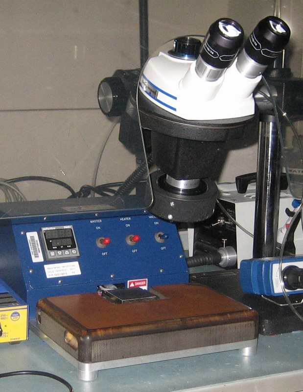

The hot plate and microscope at work.

That experiment indicated that 165 degrees C was the temperature I should use during this second experiment. Confident that Intel had used the same type of solder to attach the IHS to a Xeon processor, I set the temperature to 165 degrees C and waited until the temperature controller indicated that the heat plate had reached 160 degrees C. At that temperature, I turned on the vacuum pump that holds the device in place via a small hole in the center of the heat plate and placed the processor on the heat plate with the IHS side down. This technique limits the amount of heat absorbed by the assembly. I started applying a very light upward force on the printed circuit board using a tweezer – just enough to lift it away from the CPU when the solder had melted. The temperature of the heat plate continued to slowly increase – after about 20-30 seconds, the solder flowed and the printed circuit board lifted away from the IHS. I lifted the printed circuit board away and placed it to the side to cool.

Post-removal inspection:

During inspection of the remaining solder on the CPU, I noticed several voids or air pockets where solder was missing. In addition, there appeared to be some areas where there the solder flowed to the IHS, but had not completely bonded with it – referred to as a cold solder joint. These are process problems for Intel, but nothing to worry about going forward in this application unless they are severe. Localized over-heating in the CPU could be a problem if the voids were large, but these were small.
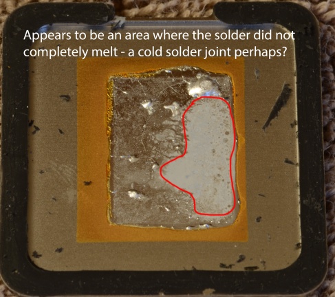
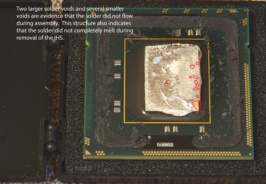
Poor soldering by Intel.

Removal of excess solder and adhesive remains:

The next task was to learn how to remove the excess solder on the CPU and the remaining adhesive from the printed circuit board. I did not want to heat the solder on the CPU with a solder iron as there is no way to know what temperature the CPU might be exposed to. Given that solder is very malleable, I decided to try using the razor blade to cut it away. This approach worked very well – only being careful to keep the blade flat against the CPU. You should not expect to see a clean gold-plated CPU at this point – a very thin layer of solder will not cause a problem in the final Mac Pro installation.

Cleaning the IHS adhesive off the printed circuit board was much more difficult. After another evening with Google, I found a video on YouTube where a Dremel tool had been used along with isopropyl alcohol. Given that the Dual Core Xeon was my test case, I elected to try this approach. I’m not convinced the alcohol is necessary as it does not soften the adhesive in the least – I elected not to use it on the W5590s. My only concern here was that static electricity could damage the CPU – to reduce that risk, I made certain that I was properly grounded with an electrostatic wrist strap. I would have no way of knowing if the processors were damaged until I had used this approach on the W5590s and installed them into the Mac Pro. I also changed the tool-head often in order to efficiently remove the material from all sides.

Post-removal inspection:

After removing the excess solder and the remaining IHS adhesive, I inspected the printed circuit board and CPU under a microscope. The inspection gave me confidence to proceed with this approach on the W5590s. The Dual Core Xeon board has only the CPU under the IHS – there are no other components. This is not the case with the Quad Core Xeon processors. As can be seen on the 2.26GHz CPU’s removed from the Early 2009 Mac Pro, there are 10 power supply bypass capacitors adjacent to the CPU. This made removing the IHS more difficult on the W5590s.
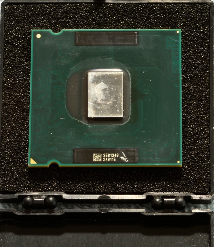

CPU with IHS, adhesive and solder removed.

Process with the Xeon W5590 CPU:

Using the approach documented here, I started work on the 3.33GHz Xeon CPU’s. All went well until the final inspection. At that point I noticed that one of the CPU’s had two damaged capacitors – I had cut into each of them while cutting the IHS adhesive. This problem was solved by purchasing a 2.26GHz Quad Core Xeon processor ( no IHS ) on eBay for $25 and using that as a donor to replace the damaged capacitors. There are 10 capacitors – each apparently 2.2 microfarads. I could have used the CPU’s that were in the Mac Pro, but I elected to keep those in case some issue came up with the W5590s when they were installed. A close visual inspection of the capacitors is important as damage there could result in the metallization layers shorting together.
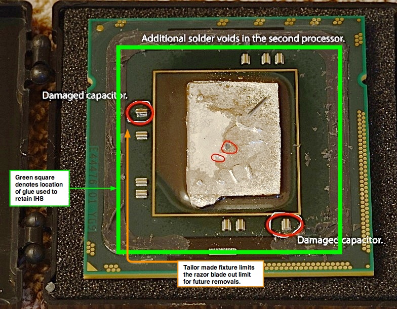

Damaged capacitors.

For future IHS removal projects, I have made a tailored jig to keep the razor blade flat with the printed circuit board. The design of the jig is such that a maximum depth of cut is maintained on all four sides, precluding damage to the surface mounted capacitors. The razor is held at an angle of 30 degrees between the two metal components with 0.260 inches of the blade extending into each channel – enough to cut the adhesive without damaging the capacitors.The fixture holds the razor blade rigid while the processor is moved, in the channel with the IHS side down, past the cutting edge. The fixture design allows the printed circuit board of the CPU to flex upward as the razor moves into the gap between the IHS and printed circuit board. (I have seen the engineering designs for Paul’s jig, and can confirm that it is exceptionally elegant. The accuracy of the tolerances suggests that there is no risk of damage to the CPU. – Ed).

If you want Paul to remove the IHS from your CPUs, you can email him in Cedar Rapids, Iowa, for more details, by clicking the icon below:


Click the icon to mail Paul Opsahl.

If you use his services, my benefit is precisely zero.

* * * * *

Thank you, Paul.

A note on temperatures. Intel’s web site states that TCase should be limited to 67C (153F to us Luddites); Paul explains that this refers to continuous use. TCase it the temperature on the outside of the IHS as Intel illustrates here:
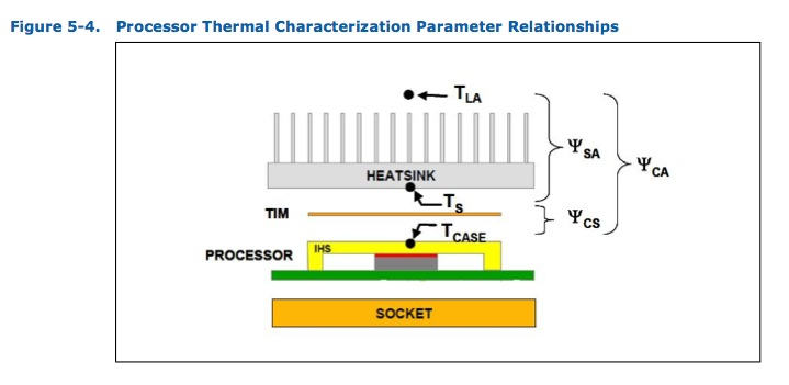

TCase for the Intel Xeon W55xx CPU family.
How then can the CPU withstand the 165C (329F) required to melt the IHS solder? Well, Intel applies that level of heat when first attaching (however ineptly) the IHS, as that’s what is needed to melt the solder in the first place. Thus application of like heat when removing the IHS should not damage the CPU provided that the period is limited. Intel’s data sheets (doubtless much beloved of Chinese intellectual property thieves, though they still have to pay Novellus and Applied Materials for the costly fabrication machinery when copying/stealing Intel’s CPU designs) have data on tolerances which lead to this conclusion. Bottom line? Don’t overheat and don’t heat for too long and you will be OK. Just enough to melt the solder and permit removal of the IHS.

Best of all, have an expert like Paul do the work for you. His 2009 Dual Core Mac Pro uses de-lidded non-IHS W5590 3.33GHz CPUs, modified using his technique above, so you can be comfortable that he eats his own cooking.